
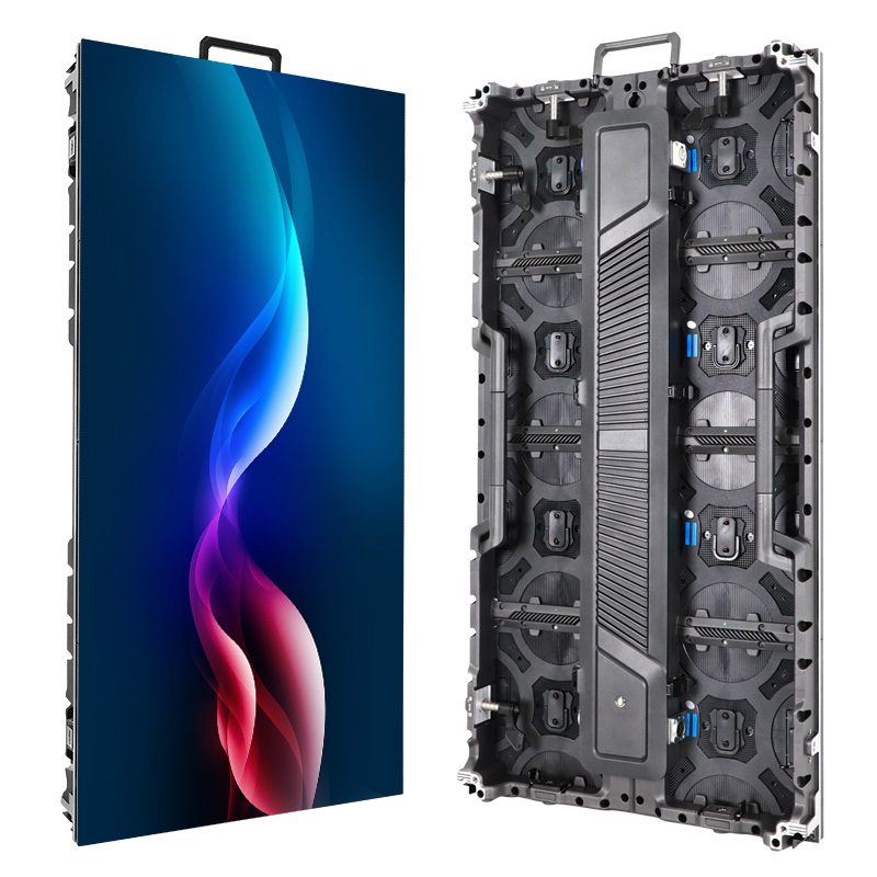
An LED receiving card is the cabinet-level control board that receives display data from a compatible sending system and distributes it to LED modules. Its configuration determines how incoming image data corresponds to the physical pixels inside the cabinet. When that configuration is wrong, a display can show scrambled images, incorrect colors, or missing sections even when the LED modules themselves are functional.
For LED display buyers, distributors, AV integrators, and project contractors, understanding this component helps prevent expensive specification mistakes. Pixel pitch and cabinet dimensions are visible purchasing criteria. Receiving card compatibility, configuration management, and replacement availability are less obvious, but they directly affect commissioning and maintenance.
Choosing an LED receiving card therefore requires more than comparing brand names or maximum pixel counts. The card must work with the controller, module electronics, HUB interface, firmware, and performance requirements of the complete display.
This guide explains what happens inside the cabinet, which specifications matter, and what to request when evaluating an EagerLED display solution or preparing a project bill of materials.
1. What Is an LED Receiving Card?
An LED receiving card is part of the control system that converts transmitted display data into the module-side signals required by a particular LED cabinet. It operates downstream of the sending device and upstream of the LED module driver circuitry.
Its responsibilities typically include interpreting pixel data, applying configured output timing, and distributing data according to the cabinet’s module arrangement. Depending on the model and system, it may also support calibration, diagnostics, and backup functions.
01. Where It Sits Inside the Cabinet
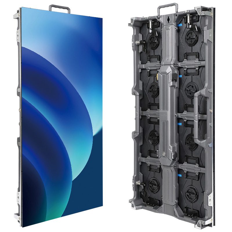
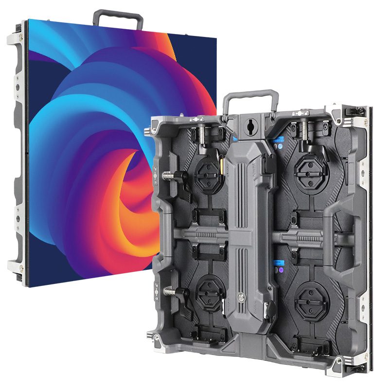
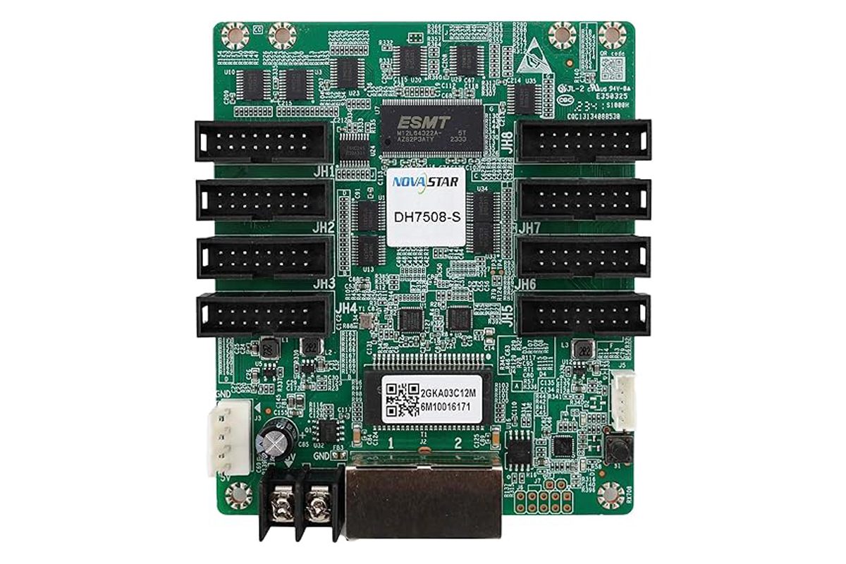
The card is usually installed in the cabinet’s electronics area, connected to a HUB board or another module interface. Some designs use a compact receiving card inserted into a separate HUB board. Others integrate receiving and module distribution functions onto one assembly.
One receiver per cabinet is common, but it is not a universal rule. Cabinet resolution, output architecture, and redundancy requirements can justify multiple receivers. Some configurations allow one receiver to serve more than one physical cabinet.
The LED receiving card also has a different job from the cabinet power supply. The power supply provides electrical energy. The receiver controls display data and timing; it does not supply the full operating power required by all the LEDs.
02. Why Buyers Should Identify the Exact Model
A quotation that says only “professional control system” leaves important questions unanswered. Buyers should know the receiving card model, hardware revision where relevant, supported controller family, and approved configuration.
That information becomes especially valuable when ordering spare parts or expanding a display months after the original installation.
2. How Does an LED Receiving Card Work?
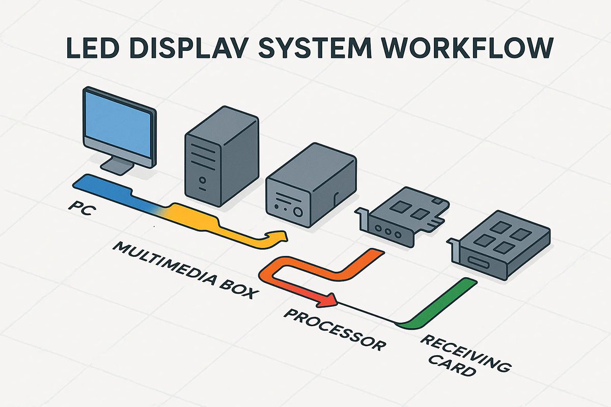
In a typical synchronous LED video wall, the signal path is:
Video source → video processor/sending device → receiving card → HUB or module interface → LED modules
Some products combine processing and sending functions in one controller. Asynchronous signage systems may use a compatible player instead of a continuously connected live video source.
01. From a Complete Image to Cabinet-Level Data
The sending system distributes image data across its output links. Screen configuration establishes which physical receiver corresponds to each image region.
The LED receiving card processes the relevant data and outputs it according to the cabinet configuration. Module driver ICs then control the electrical drive of the LEDs.
Two configuration layers are important:
| Configuration layer | What it describes | Typical symptom when incorrect |
|---|---|---|
| Module and receiver parameters | Driver IC, scan arrangement, data groups, output timing | Scrambled pixels, missing rows, incorrect colors |
| Screen connection mapping | Cabinet position and connection order within the wall | Swapped cabinets, misplaced image sections |
A working data connection does not prove that either layer is correct. A receiver may communicate with the controller while displaying an unusable image.
02. Mapping Pixels to Physical Modules
Consider a hypothetical cabinet containing modules arranged in two columns and two rows. The receiver needs the correct output assignment and internal module mapping. The wall configuration separately needs the cabinet’s location relative to neighboring cabinets.
If these layers are confused, technicians may try to repair a cabinet-position problem by changing module parameters. That can introduce additional faults.
For commissioning, treat the LED receiving card configuration and the overall screen map as separate, related records. EagerLED’s mixed-size rental screen tutorial similarly distinguishes loading a prepared receiving configuration from arranging the screen connection.
3. Receiving Card Connections and Cabinet Wiring
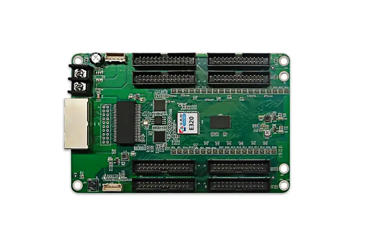
An LED receiving card normally connects to low-voltage DC power, the display data link, and module output circuitry. Connector layout varies considerably between designs, so wiring should follow the exact cabinet drawing and card documentation.
01. Understand Each Connection
| Connection or component | Purpose | What to verify |
|---|---|---|
| Data-link connector | Receives and forwards display data where supported | Supported topology, port roles, cable condition |
| DC power connection | Powers receiver electronics | Specified voltage, polarity, termination |
| High-density board connector | Connects a compact receiver to its HUB board | Matching interface, orientation, seating |
| Ribbon cable or module output | Carries control signals toward modules | Pin assignment, orientation, port order |
| Status indicators | Reports power or operating conditions | Model-specific meaning of each pattern |
Some receivers expose RJ45 ports directly. Others connect through a HUB assembly that carries the external connectors.
An RJ45 connector does not establish compatibility with ordinary office networking. Use switches, converters, or other network equipment only when the control-system manufacturer supports that arrangement.
02. The HUB Board’s Role
A HUB board routes connections between the receiving electronics and LED modules. Depending on the cabinet design, it may also carry power distribution, monitoring connections, or additional circuitry.
Matching connector shapes alone is insufficient. Two boards can look similar while using different pin assignments or signal arrangements.
For an LED receiving card replacement, verify the complete receiver-and-HUB combination. Forcing an apparently compatible board into the wrong assembly can damage equipment.
03. Wiring for Maintainability
Cabinet wiring should allow technicians to identify the receiver, trace module outputs, and replace a component without disturbing unrelated connections.
Label data direction and module ports, retain a wiring diagram, and provide appropriate strain relief. Route cables so they are not pinched by cabinet doors or service covers.
Disconnect power before reseating boards or changing internal connections unless the manufacturer explicitly supports that service procedure under power.
4. Key Receiving Card Specifications Explained
The headline specification for an LED receiving card is often its loading capacity. That is useful, but a professional evaluation also needs dimensional limits, module compatibility, and operating conditions.
01. Pixel Loading Capacity and Dimensional Limits
Pixel load is calculated from the resolution assigned to the receiver:
Pixel load = pixel width × pixel height
A hypothetical 192 × 192-pixel cabinet contains 36,864 pixels. This calculation identifies the required load; it does not establish that any particular receiver can operate the cabinet.
Check all applicable restrictions:
- Total supported pixel count.
- Maximum supported width and height.
- Available module output groups.
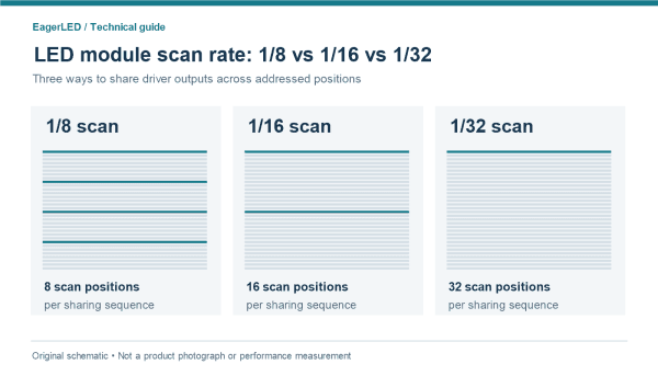
- Driver IC and scan-mode support.
- Capacity under the required frame rate, bit depth, and enabled features.
A long, narrow cabinet can meet the total pixel limit while exceeding a width restriction. A module arrangement can also require more output groups than the card provides.
02. Read Specifications as a Combination
| Specification | Why it matters | Question for the supplier |
|---|---|---|
| Pixel loading capacity | Establishes the supported image area | Under which operating conditions is this capacity valid? |
| Maximum width and height | Limits unusual cabinet layouts | Does the proposed mapping meet both limits? |
| Output groups and interfaces | Determines module connectivity | Does the receiver match this HUB and module layout? |
| Driver IC and scan support | Enables correct module operation | Has this exact module combination been validated? |
| Grayscale performance | Influences tonal reproduction | How does the complete cabinet perform at low brightness? |
| Refresh performance | Affects temporal display behavior | What does the assembled display achieve? |
| Firmware compatibility | Controls supported functions | Which approved version should be used? |
03. Refresh Rate Is Not Video Frame Rate
Video frame rate describes how often source images change. LED refresh rate describes aspects of how the display drive repeats over time. They are related system considerations, but they are not interchangeable measurements.
Camera performance also depends on scan behavior, driver timing, brightness settings, camera shutter settings, and synchronization.
An LED receiving card cannot independently guarantee a camera-ready display. Require a demonstration using the intended cabinet configuration and representative camera conditions.
Likewise, a processing bit-depth claim should not be treated as proof of visible grayscale quality. Inspect dark gradients and low-brightness content on the assembled screen.
5. LED Receiving Card vs. Sending Card vs. HUB Board
These components are often grouped together in quotations, although their functions differ.
| Component | Main responsibility | Typical location | Selection concern |
|---|---|---|---|
| Video processor | Handles supported source selection, scaling, and image processing | Equipment rack or controller enclosure | Input formats and processing requirements |
| Sending card or sending device | Transmits display data to compatible receivers | Controller or separate sending unit | Output capacity and receiver compatibility |
| LED receiving card | Controls cabinet-level pixel output | Inside the cabinet | Module support, timing, and configuration |
| HUB board | Routes connections between receiver and modules | Inside the cabinet | Electrical interface and physical compatibility |
| LED module | Contains LEDs and associated drive circuitry | Display surface | Optical and electrical characteristics |
An all-in-one controller can combine the first two roles. An integrated receiving assembly can combine receiving and HUB functions.
01. Integrated and Separate Designs
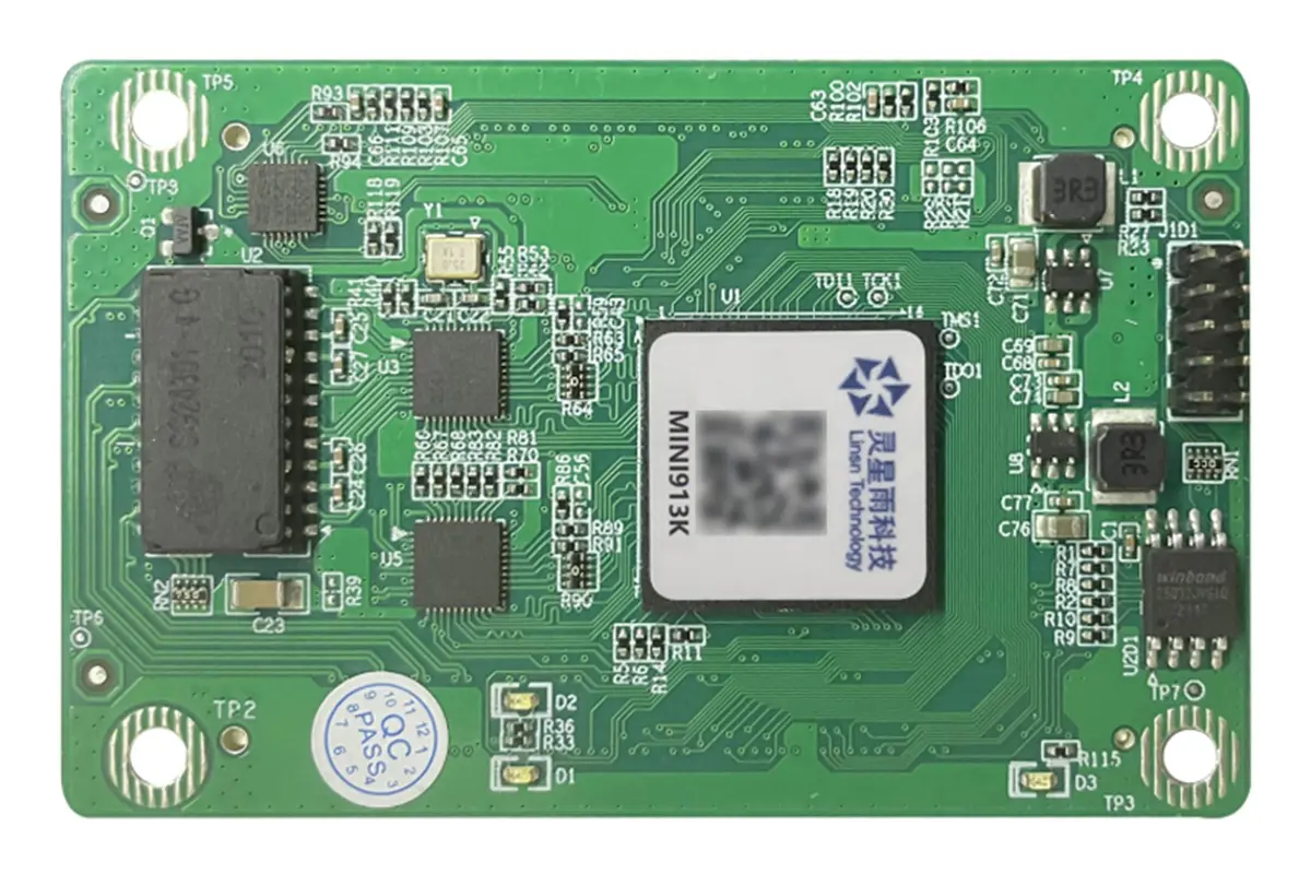
Separate receiver and HUB designs can make it possible to replace one component without replacing the other. They can also provide flexibility across cabinet layouts. However, they introduce a board-to-board connection and require careful interface matching.
Integrated designs can simplify internal assembly and reduce separate interconnections. Their maintenance implications depend on what must be replaced when one function fails.
Neither architecture is automatically better. Evaluate service access, spare-part cost, connector reliability, and supplier support for the actual cabinet.
02. Brand Names Do Not Establish Interoperability
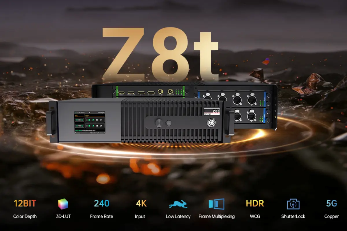
NovaStar, Colorlight, and other control-system brands offer multiple product families. Compatibility should be checked at the controller, receiver, hardware, and firmware level.
Do not assume an LED receiving card will work with a sending device simply because both carry the same brand name. Similarly, receivers from different ecosystems should not be treated as interchangeable without explicit manufacturer support.
For distributors, a documented compatibility matrix is more useful than a broad statement that a cabinet uses a “standard receiver.”
6. Advanced Features: Benefits and Limitations
Advanced LED receiving card features can improve image consistency and serviceability. Their value depends on whether the complete cabinet and control system support them.
01. Brightness and Color Calibration
Calibration uses measured correction data to reduce visible differences between pixels or modules. Supported systems can store or apply coefficients through different parts of the display architecture.
This can help maintain uniformity, but calibration cannot repair failed LEDs or eliminate every difference between mismatched module batches.
When evaluating an LED receiving card, ask where calibration data resides, how it is backed up, and what happens after replacing a receiver or module. A generic cabinet configuration file should not be assumed to contain every calibration record.
02. Redundancy Protects Specific Failure Paths
A looped data path, a backup receiver, and a redundant power supply address different faults.
| Feature | Potential benefit | Limitation to understand |
|---|---|---|
| Data-link redundancy | Maintains data delivery after certain link failures | Does not automatically protect against receiver failure |
| Dual-receiver backup | Provides a supported alternate receiving path | Requires compatible hardware, wiring, and configuration |
| Calibration-data backup | Helps recover correction information | Does not correct physical module faults |
| Operating-status monitoring | Helps identify abnormal conditions | Available measurements depend on hardware and sensors |
| Reduced-latency operation | Can reduce delay within supported configurations | Does not define total source-to-screen latency |
NovaStar’s A8s specifications document model-specific operating and redundancy behavior. Features from one product’s datasheet should not be generalized to every receiver.
03. Test the Failure You Intend to Cover
For a mission-critical installation, define the required response to a cable break, controller outage, receiver fault, or power failure.
Then validate the relevant scenarios during acceptance testing under an approved procedure. A quotation containing the word “redundancy” is not enough to establish what remains operational after a fault.
The same approach applies to latency: measure the complete signal path when timing matters.
7. How to Choose an LED Receiving Card
Start with the project’s display and operating requirements. Then select an LED receiving card as part of a validated cabinet configuration.
01. Match the Application
| Application | Main priorities | Useful acceptance check |
|---|---|---|
| Rental and touring | Fast servicing, repeatable mapping, compatible spare stock | Replace a receiver and restore the cabinet |
| Corporate and conference spaces | Stable operation and good low-brightness images | Inspect gradients at normal room brightness |
| Broadcast and virtual production | Camera behavior, timing, synchronization | Test with the intended camera setup |
| Outdoor fixed displays | Suitable cabinet protection and service access | Review environmental suitability of the full cabinet |
| Retail signage networks | Consistent configurations and maintainable hardware | Verify identification and recovery procedures |
An outdoor project does not necessarily require a receiver marketed as “outdoor.” Environmental suitability depends on the receiver’s ratings and the protection, cooling, and operating conditions provided by the cabinet.
02. Specify the Complete Compatibility Chain
Before purchase, verify the following sequence:
Controller → receiver model → HUB/interface → module electronics → approved configuration
Ask the supplier to confirm this combination in writing. Include the required resolution, intended video format, brightness operating range, and any camera or latency requirements.
The LED receiving card should be evaluated alongside the cabinet, not purchased as an isolated upgrade based on a larger advertised capacity.
03. Request a Practical Documentation Package
For an EagerLED project inquiry, provide display dimensions, pixel pitch, application, installation environment, and preferred control ecosystem. Request the exact receiver configuration proposed for that project.
| Requested item | Why it matters |
|---|---|
| Receiving card model and relevant revision | Identifies the installed component |
| Controller and firmware compatibility record | Reduces uncertainty during updates or expansion |
| Approved cabinet configuration | Enables repeatable setup and recovery |
| Screen connection drawing | Documents cabinet order and output assignment |
| Calibration backup procedure | Supports maintenance without losing correction data |
| Spare-parts list and substitution rules | Prevents unsuitable replacements |
| Acceptance-test requirements | Defines what must be demonstrated before handover |
04. Compare Lifecycle Cost
A lower LED receiving card purchase price may be offset by difficult sourcing, limited documentation, or longer recovery time.
Distributors should consider whether different cabinet batches can share spare stock. Contractors should consider who will restore the display after handover and whether that team has the necessary files and software.
Do not choose a generic spare percentage without considering downtime tolerance, installed quantity, service access, and replenishment time. The important outcome is a supported replacement strategy.
8. Receiving Card Setup and Troubleshooting
A repeatable commissioning process is more valuable than repeatedly adjusting settings until an image appears.
01. Establish a Known Configuration
Before changing an operational display, record the installed hardware and back up accessible settings. Obtain the supplier-approved files for the actual module and receiver combination.
A practical setup sequence is:
- Inspect cabinet wiring and confirm specified power requirements.
- Establish communication using compatible control software.
- Apply the approved LED receiving card parameters.
- Verify one cabinet before extending changes across the wall.
- Configure screen connection order and image placement.
- Apply or restore calibration through the supported procedure.
- Save settings as required and verify operation after a controlled restart.
Software commands and file formats vary by ecosystem. EagerLED’s Colorlight software guidance recommends recording hardware details, backing up parameters, and testing updates before wider deployment.
02. Diagnose by the Area Affected
The size and location of a fault can help narrow the investigation. One affected module suggests a different starting point from an entire downstream cabinet chain.
| Symptom | Possible causes | First checks |
|---|---|---|
| One cabinet is black | Local power, data interruption, configuration, receiver fault | Power indicators, connections, receiver detection |
| Several consecutive cabinets are black | Upstream link or shared power problem | First affected point and preceding cabinet |
| One module is abnormal | Module fault, ribbon cable, HUB output | Local connection and controlled substitution |
| Cabinet displays the wrong image region | Incorrect screen mapping | Cabinet order and assigned position |
| Colors or rows are scrambled | Incorrect parameters or output connection | Approved file, module type, cable orientation |
| Intermittent flickering | Power instability, connection issue, timing mismatch | Whether the fault follows power, cable, or configuration |
| Replaced cabinet appears brighter | Calibration or brightness-setting mismatch | Correction data and relevant display settings |
These symptoms are diagnostic clues, not proof that the LED receiving card has failed.
03. Replace Without Losing the Working Reference
When replacing an LED receiving card, record its model and relevant firmware information, label connections, and retain the original board for investigation.
Use an approved replacement, then restore configuration and calibration as separate tasks where the system requires it. Check full-color fields, grayscale ramps, fine patterns, and representative content.
Avoid copying every available setting from a neighboring cabinet without understanding it. Module parameters may match, while image position or calibration information may differ.
Finish by checking the whole wall. A repaired cabinet can display correctly in isolation while remaining incorrectly mapped within the installation.
9. FAQ
01. Can an LED receiving card store videos for offline playback?
A conventional LED receiving card is not normally the content-storage device. Offline scheduling and media storage generally belong to an asynchronous player or another compatible controller. Integrated products can combine roles, so confirm the system architecture. Ask which component stores the media and what happens when the external source or management connection is unavailable.
02. Can I connect a laptop directly to a receiving card?
A laptop’s ordinary network port is not a universal substitute for the required sending system. Some products support manufacturer-specific direct communication or configuration workflows, but these should not be confused with standard video playback. Follow the documented architecture for the exact receiver and software combination.
03. Does a receiving card determine the screen’s pixel pitch?
No. Pixel pitch is the physical spacing between adjacent pixels on the LED module. The receiver must support the resulting module resolution and electronics, but changing the card does not alter that spacing. A finer-pitch display may require a different receiving arrangement because more pixels occupy the same physical area.
04. Will a higher-capacity receiver make the display sharper?
Not by itself. Sharpness depends on factors including physical pixel density, source resolution, scaling, and viewing distance. A higher-capacity LED receiving card can support a suitable load or enable supported functions, but it cannot add physical pixels to existing modules. Upgrade only to solve a defined compatibility or performance requirement.
05. Should receiving card firmware always be updated?
No. Use firmware approved for the installed hardware and required functions. An update should have a defined purpose, such as addressing a documented issue or enabling a supported feature. Record the current version, preserve configuration files, and confirm the recovery procedure. Test the change on suitable spare equipment before deploying it across an operational wall.
06. How do I identify an undocumented receiving card?
Start with clear photographs of the board label, connectors, and revision markings while following safe service procedures. Compatible software may also report identifying information. Send these details, together with the controller and module information, to the original supplier. Do not select an LED receiving card replacement from board color or connector appearance alone.
07. What files should an integrator hand over after installation?
The handover should include approved receiver parameters, the screen connection map, hardware identification, relevant software and firmware versions, and the calibration backup or recovery procedure. Add wiring drawings and replacement instructions. Label files by project and cabinet type so a future technician can identify the correct version without trial and error.
08. What determines the price of an LED receiving card?
Pricing depends on the product family, supported functions, supply channel, order quantity, and support arrangement. Compare quotations for the exact approved model and clarify whether configuration assistance or associated HUB hardware is included. For project purchasing, also evaluate availability and restoration time; a cheaper unsupported substitute can create a larger service expense.
10. Conclusion
An LED receiving card connects the control system to the physical operation of an LED cabinet. Selecting it correctly requires matching pixel load, module electronics, interfaces, firmware, and project requirements—not simply choosing the highest number on a specification sheet.
For buyers and integrators, the strongest purchasing evidence is a validated cabinet configuration supported by clear documentation and repeatable acceptance tests. For distributors, compatible spare stock and reliable recovery procedures matter just as much as initial component cost.
When discussing an EagerLED display project, request the exact LED receiving card model, compatibility details, configuration package, and replacement process. Those details help turn a working display at delivery into a system that remains practical to operate, expand, and maintain.
 Best LED Display Manufacturers in China: How to Choose a Reliable Supplier