
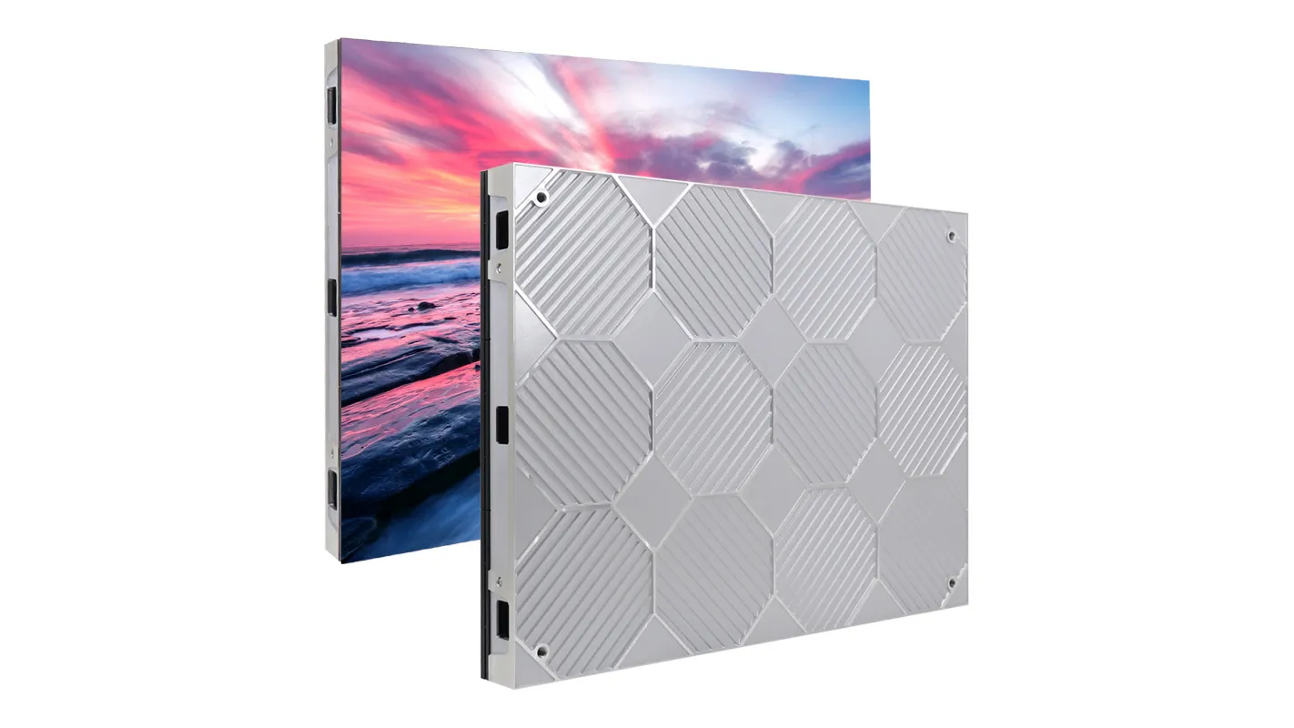
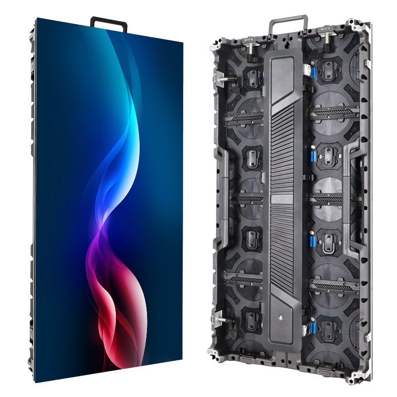
The HUIDU HD-VP1240A LED video processor is a 2-in-1 controller for configuring and driving LED displays without a separate sending box. It combines video processing with 12 Gigabit Ethernet outputs, controls up to 7.8 million pixels, accepts selected 4K@60Hz sources, and supports four independent windows. A reliable setup follows one order: connect the source and receiving cards, install HDSet, load the receiving-card parameters, map every output port, and then verify the display with a test pattern.
This guide explains that complete workflow for technicians, integrators, rental teams, and first-time operators. It also answers the Search Console demand behind HDSet screen configuration and no signal searches with practical checks rather than generic advice. The specifications below are cross-checked against the Shenzhen Huidu Technology product page and the official HUIDU instruction-manual center.
Contents
- HD-VP1240A overview and specifications
- Equipment and information to prepare
- How to connect the hardware
- How to install HDSet and connect
- HDSet screen configuration
- Input sources and four-window display
- No-signal and display troubleshooting
- Operating and maintenance checklist
- Frequently asked questions
1. HD-VP1240A Overview and Specifications
01. What the HD-VP1240A does
The HD-VP1240A is designed for synchronous LED display systems that need several source formats, large pixel capacity, and flexible layouts. Its 2-in-1 architecture receives and scales video, then sends RGB data directly to receiving cards through 12 network ports. This removes one device and one signal handoff from the rack compared with a separate processor and sender.
The unit is suitable for conference rooms, exhibition booths, studios, retail LED walls, event stages, and other installations where the displayed content must follow a live source. Built-in Wi-Fi supports mobile-app control, while USB-B is the normal service connection for HDSet. RS232 is available when the HD-VP1240A must join a central control system.
02. Capacity limits that matter in design
Three limits must be checked together: total pixel load, canvas width or height, and the load assigned to each Ethernet output. The HD-VP1240A can control 7.8 million pixels in total, with a maximum canvas width of 16,000 pixels and a maximum height of 4,000 pixels. Each output port controls up to 650,000 pixels. A screen can therefore fit the total load but still fail if one port is assigned too many pixels.
| Specification | HD-VP1240A value | Installation meaning |
|---|---|---|
| Controller type | 2-in-1 video processor and sender | No separate sending controller is required |
| Total loading capacity | 7.8 million pixels | Total mapped output must remain at or below this limit |
| Maximum canvas | 16,000 px wide; 4,000 px high | Useful for ultra-wide LED walls and banners |
| Network outputs | 12 x Gigabit Ethernet | Each port can feed receiving-card chains |
| Per-port load | 650,000 pixels maximum | Balance cabinet rows or columns across ports |
| Display layers | Up to 4 windows | Four sources can share one canvas in a custom layout |
| Scene presets | 8 | Save recurring source and window arrangements |
| Control | USB-B, RS232, Wi-Fi, IR | Use USB-B for initial HDSet configuration |
| Power and environment | AC 100-240V, 50/60Hz; 50W; -10°C to 60°C | Confirm rack power, ventilation, and ambient conditions |
2. Equipment and Information to Prepare Before Setup
01. Hardware checklist
Prepare every cable and configuration file before powering the system. This shortens commissioning time and prevents a missing receiving-card file from being mistaken for an HD-VP1240A fault. Use known-good Cat5e or better Ethernet cables for short indoor runs, and follow the LED system supplier’s cable-distance and shielding requirements for the actual venue.
| Item | Why it is required | Check before connection |
|---|---|---|
| HD-VP1240A and power cable | Processes video and sends LED data | Correct model, undamaged connectors, stable rack position |
| LED cabinets and receiving cards | Display the mapped output | Known cabinet resolution and card model |
| Computer with HDSet | Performs screen configuration and port mapping | Administrator rights and a working USB port |
| USB-B cable | Connects the service computer to the processor | Data-capable cable, not a charge-only lead |
| HDMI, DP, Type-C, or DVI cable | Carries the selected source signal | Matches the source resolution and connector standard |
| Ethernet cables | Connect the 12 outputs to receiving-card chains | Label both ends with port and cabinet destination |
| Receiving-card configuration file | Defines module scan, color, timing, and cabinet parameters | Supplied for the exact cabinet batch |
| Screen map | Records cabinet rows, columns, and cable direction | Total width, height, and each port’s assigned area |
02. Calculate the screen before opening HDSet
Write down the cabinet pixel width, cabinet pixel height, number of cabinet columns, and number of cabinet rows. Multiply cabinet width by columns to get total screen width; multiply cabinet height by rows to get total screen height. Then multiply those two totals to obtain the pixel load.
For example, a 20-column by 10-row wall using 192 x 192 pixel cabinets produces a 3840 x 1920 canvas, or 7,372,800 pixels. That fits the HD-VP1240A total capacity. A 3840 x 2160 canvas contains 8,294,400 pixels and exceeds 7.8 million, even though it fits within the separate width and height ceilings. This calculation should be completed before port mapping.
3. How to Connect the HD-VP1240A to an LED Screen
01. Connect the video source
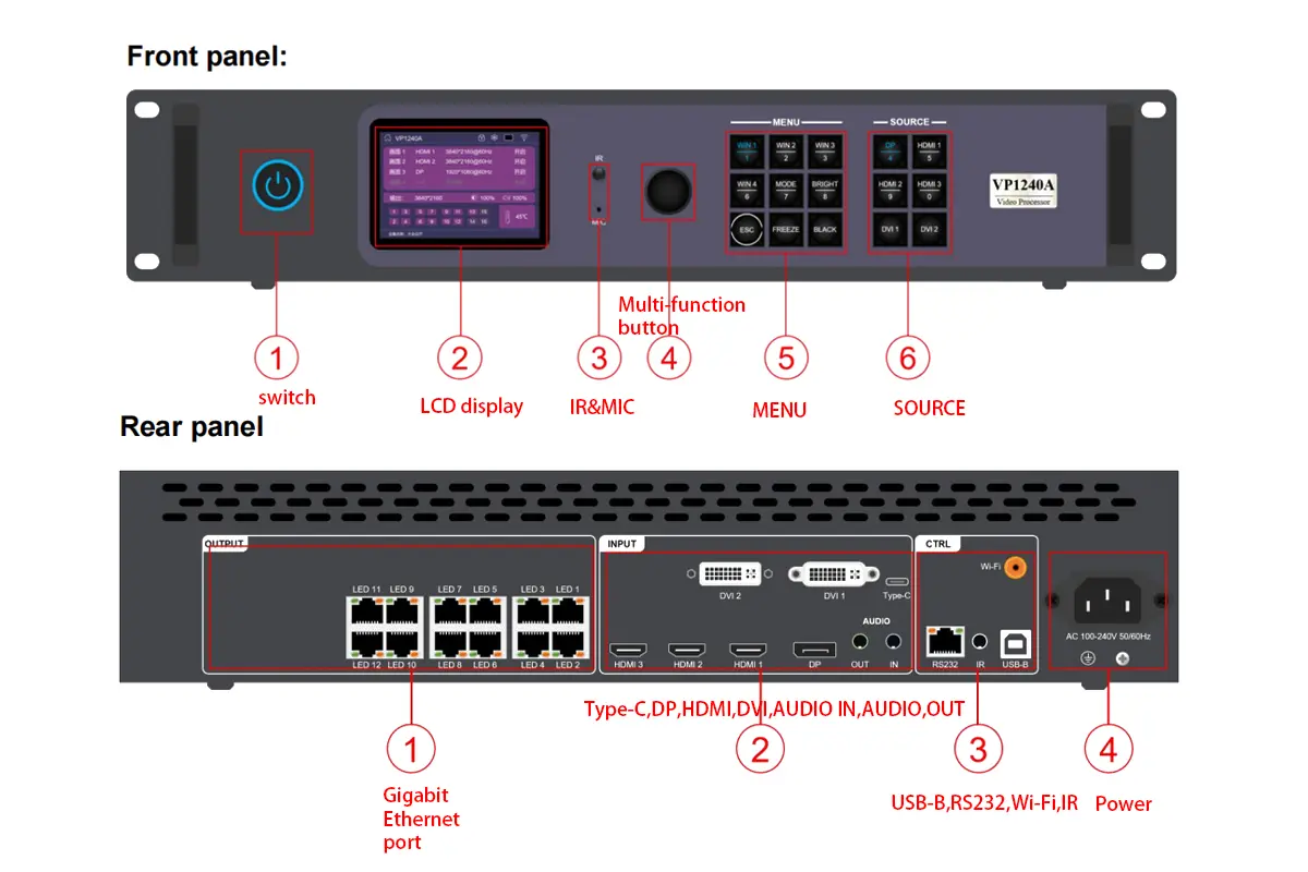
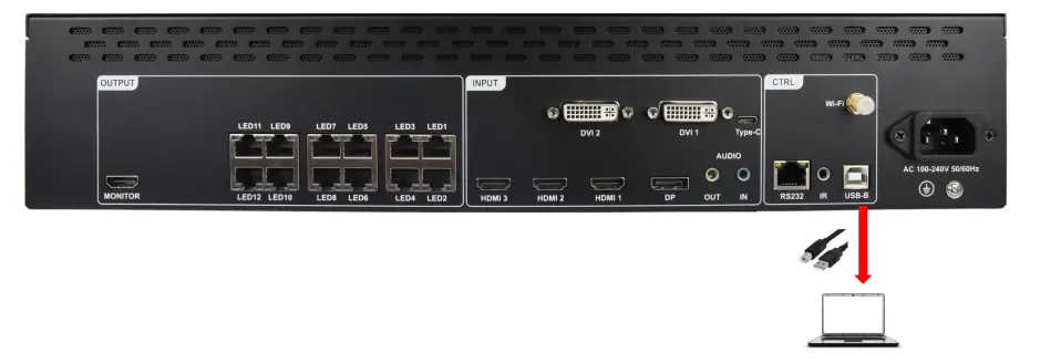
With power off, connect the playback computer, media server, camera switcher, or other source to the appropriate input. HDMI 1 is the HDMI 2.0 input and supports up to 3840 x 2160 at 60Hz. HDMI 2 and HDMI 3 are HDMI 1.4 inputs and support up to 3840 x 2160 at 30Hz. DP and Type-C support up to 3840 x 2160 at 60Hz, but they share one channel and cannot be active simultaneously.
If Type-C is required, enable it in Advanced Settings because DP is the default for the shared channel. DVI is useful for 1920 x 1080 computer or 1080p video sources. Embedded digital audio can travel with supported HDMI, DP, or Type-C signals; use the 3.5 mm AUDIO IN only when analog audio is needed.
02. Connect the 12 Ethernet outputs
Connect OUT1 through OUT12 on the HD-VP1240A to the first receiving card in each planned cabinet chain. Follow the physical cable order recorded on the screen map. Do not assume the software can compensate for undocumented wiring: port mapping is faster and safer when the labels on the cables match the map in HDSet.
Keep each chain below 650,000 pixels. If a cabinet row is larger than that limit, split the row between two outputs or divide the wall by columns. Avoid connecting or disconnecting Ethernet cables while commissioning changes are being sent to receiving cards.
03. Connect control, audio output, and power
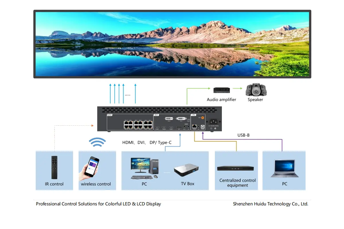
Connect the configuration computer to USB-B. If the installation uses centralized automation, wire RS232 according to the control-system design. For sound reinforcement, connect AUDIO OUT to an amplifier or powered speaker; the processor’s analog output is not intended to drive passive speakers directly.
Attach the Wi-Fi antenna if mobile control will be used. Verify AC power matches 100-240V at 50/60Hz, switch on the source and LED cabinets, and power the HD-VP1240A last. The front LCD should show device and source status. At this stage a blank wall is normal until receiving-card data and port mapping are correct.
4. How to Install HDSet and Establish Communication
01. Install a compatible HDSet release
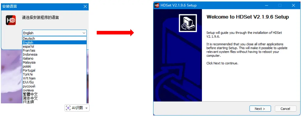
Download HDSet from the HUIDU software download page or the manufacturer’s current software center. Keep the installer and the receiving-card file in a project folder so the system can be serviced later. Close other LED configuration tools before installation because competing drivers can prevent the HD-VP1240A from appearing.
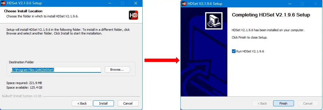
Run the installer, select the required language, accept the destination folder, and finish the setup. If Windows requests a device driver, allow the signed HUIDU component to install. Restart HDSet after driver installation rather than repeatedly unplugging the processor.
02. Connect HDSet to the processor
Use a data-capable USB-B cable, launch HDSet, and wait for the device list to populate. Select the HD-VP1240A and open the processor control interface. If no device appears, try a different USB port, confirm the cable supports data, and check Windows Device Manager for the controller or an unresolved driver.
Do not begin by changing source scaling. First confirm that HDSet reads the model and current status. This separates a computer-to-processor communication problem from a processor-to-screen mapping problem. Once communication is stable, save or record the current project before overwriting an existing installation.
03. Verify the software connection
- The device list identifies HD-VP1240A rather than a different controller.
- The processor status or input page updates when a front-panel source is changed.
- The screen-configuration page opens without a communication timeout.
- The software can read current firmware information before any upgrade is attempted.
5. HDSet Screen Configuration for the HD-VP1240A
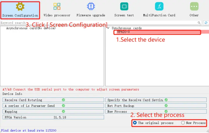
01. Load the receiving-card parameters
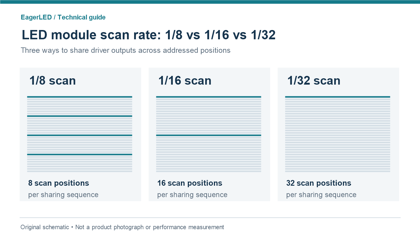
Open Screen Configuration and load the receiving-card parameter file supplied for the exact LED cabinets. These parameters control scan mode, module arrangement, data polarity, color order, and timing. A wrong file may produce duplicated rows, incorrect colors, flicker, or a completely dark panel even when the HD-VP1240A is sending data correctly.
Send the receiving-card parameters to a small test chain first. Confirm one cabinet displays the built-in test pattern correctly before mapping the full wall. This is the fastest way to isolate cabinet configuration from Ethernet port layout.
02. Enter the total screen dimensions
Set the total canvas width and height from the cabinet calculation. The product limit is not a target: leave headroom when practical and verify that width multiplied by height remains at or below 7.8 million pixels. The HD-VP1240A accepts custom ultra-wide canvases as long as total load, 16,000-pixel width, 4,000-pixel height, and per-port limits are all respected.
03. Map every Ethernet port
For each active output, enter its horizontal start position (X), vertical start position (Y), width, and height. X and Y describe where the port begins on the full canvas, not where the cabinet sits in the room. Adjacent port areas should meet without a gap or overlap unless the creative layout intentionally requires one.
| Screen example | Total pixels | Suggested mapping logic | Result |
|---|---|---|---|
| 1920 x 1080 | 2,073,600 | Use 4 ports at about 518,400 pixels each | Within total and per-port limits |
| 3840 x 1080 | 4,147,200 | Use 8 balanced areas at about 518,400 pixels each | Within HD-VP1240A capacity |
| 3840 x 1920 | 7,372,800 | Use all 12 ports at about 614,400 pixels each | Valid but close to the total limit |
| 3840 x 2160 | 8,294,400 | Cannot be solved by adding ports | Exceeds 7.8 million pixels |
| 7680 x 900 | 6,912,000 | Split the ultra-wide canvas across 12 balanced chains | Within width, height, and total limits |
After mapping, send the configuration to the processor and receiving cards, then run red, green, blue, white, and grid test patterns. A grid immediately reveals missing columns, swapped cable order, overlaps, and start-coordinate errors. Save the finished HDSet project, the receiving-card file, a screenshot of the port map, and the firmware versions together.
6. Input Sources and Four-Window Display
01. Choose the correct input interface
Select the input that matches both source capability and required refresh rate. A source can report 4K while actually outputting 30Hz, an unsupported color format, or an unstable adapter conversion. Check the processor LCD and HDSet input status before changing LED mapping.
| Input | Quantity | Maximum stated resolution | Important note |
|---|---|---|---|
| HDMI 2.0 | 1 (HDMI 1) | 3840 x 2160@60Hz | Preferred for a common 4K60 source |
| HDMI 1.4 | 2 (HDMI 2/3) | 3840 x 2160@30Hz | Use 1080p60 when motion at 60Hz is more important than 4K |
| DisplayPort 1.2 | 1 shared channel | 3840 x 2160@60Hz | DP is the default mode for the shared DP/Type-C channel |
| Type-C | 1 shared channel | 3840 x 2160@60Hz | Enable in Advanced Settings; source must support DP Alt Mode |
| DVI-I | 2 | PC up to 1920 x 1080; video up to 1080p | Useful for established 1080p production systems |
02. Build a four-window layout
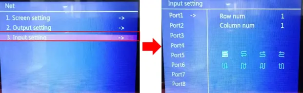
The HD-VP1240A supports up to four display windows. Select WIN1 through WIN4 from the front panel or in HDSet, assign an input to each window, and define each window’s X position, Y position, width, and height. A window may scale its source to fit the assigned region; for the sharpest result, match the source crop or output resolution to the window’s pixel dimensions.
Use one window for a full-screen background and the others for picture-in-picture only when the intended layer order is verified. For a four-quadrant dashboard, calculate each quadrant from the final canvas and keep boundaries on whole pixels. Save the finished arrangement as one of eight scene presets so an operator can recall it without reopening HDSet.
03. Use capture, freeze, black, and presets safely
Capture selects a region from a larger input, which is useful when a media server provides a composite canvas. Freeze holds the current frame during source changes; BLACK removes the image from the LED wall while keeping the system configured. Neither function repairs a missing input. If the HD-VP1240A reports no signal, verify the source and cable before assuming FREEZE or BLACK is active.
7. HD-VP1240A No-Signal and Display Troubleshooting
01. Diagnose in signal-flow order
Troubleshoot from source to screen: source output, input cable, processor input status, processor output mapping, receiving-card chain, and cabinet power. Changing several settings at once destroys the evidence needed to locate the fault. Use the front LCD, HDSet status, test patterns, and one known-good cabinet as checkpoints.
| Symptom | Most likely checks | Corrective action |
|---|---|---|
| HDSet cannot find HD-VP1240A | USB-B cable, Windows driver, USB port, competing software | Use a data cable, reinstall the driver, reconnect, and relaunch HDSet |
| Processor shows no signal | Wrong source selected, unsupported source timing, bad cable, DP/Type-C mode | Select the physical input, test 1920 x 1080@60Hz, replace cable, verify shared-channel setting |
| All cabinets are black but input is detected | BLACK function, receiving-card file, no output map, cabinet power | Exit BLACK, load correct card data, send mapping, and verify power |
| Only one area is black | Port cable, chain order, port start coordinate, per-port dimensions | Swap with a known-good cable and compare the affected port map |
| Image repeats or is offset | Cabinet width/height, X/Y starts, cable direction | Correct cabinet parameters and rebuild the port sequence |
| Colors are wrong | Receiving-card color order or parameter file | Use the exact cabinet file; do not compensate with source color controls |
| Flicker or intermittent blocks | Marginal Ethernet cable, excessive chain load, unstable power, card timing | Shorten or replace cable, rebalance load, test power, verify card parameters |
| 4K source works at 30Hz but not 60Hz | Input type, cable bandwidth, source format, adapter limitation | Use HDMI 1, DP, or Type-C; confirm 4K60 cable and source capability |
02. Recovery sequence for a blank screen
- Set the source temporarily to 1920 x 1080@60Hz and verify it on another monitor.
- Connect it directly to a known input on the HD-VP1240A and select that input.
- Confirm the LCD or HDSet reports the incoming resolution.
- Enable an internal test pattern. If the pattern displays, the output path works and the fault is upstream.
- If the pattern does not display, test one output, one cable, and one known-good cabinet with the correct receiving-card file.
- Rebuild the full port map only after the single-cabinet test passes.
03. When to reset or update firmware
A factory reset is appropriate when configuration history is unknown or a repeatable software setting cannot be explained. Record the current map and files first because the reset removes working parameters. Firmware should be updated only with a package intended for the exact HD-VP1240A hardware version and a stable power supply; firmware is not a first response to a cable or mapping fault.
8. Operating and Maintenance Checklist
01. Before every event or operating day
| Stage | Check | Pass condition |
|---|---|---|
| Power | AC feed, rack ventilation, processor temperature | Stable power and unobstructed airflow |
| Source | Selected input, resolution, refresh rate, audio | HD-VP1240A detects the expected timing |
| Output | All 12 cable labels and link paths | Each active chain matches the saved screen map |
| Display | Grid and RGBW test patterns | No missing, repeated, swapped, or discolored areas |
| Scenes | Recall every required preset | Windows, sources, and sizes match the event plan |
| Backup | HDSet project, receiving-card file, mapping screenshot | Copies are available on the service computer and project storage |
02. Configuration records to keep
Store the processor serial number, firmware versions, HDSet version, receiving-card model, cabinet resolution, screen dimensions, port assignments, source formats, and the date of the last verified configuration. These records turn an emergency rebuild into a controlled restore. They also help a new technician distinguish the intended design from a temporary event-day change.
The HD-VP1240A specification notes that standard and high-end versions may differ and that product appearance can vary. Confirm optional SDI or USB functions with the supplier for the specific unit rather than assuming every rear panel is identical. This limitation should be checked before procurement or rack wiring.
9. HD-VP1240A FAQ
Final setup rule: validate one known-good source, one HD-VP1240A input, one Ethernet output, and one cabinet before expanding to the full wall. This controlled sequence prevents source, processor, mapping, and receiving-card faults from being mixed together. For a new installation or a replacement controller, keep the completed HDSet project and port map with the system documentation.
 Top 15 LED Screen Suppliers in Japan (2026 Guide)
 Top 10 German LED Display Suppliers in 2026