
An LED display rarely fails in a convenient way. A dark pixel appears before a showroom opening, a horizontal line interrupts a conference backdrop, or a replacement module looks warmer than the surrounding screen. For distributors, AV integrators, and project contractors, the challenge is to identify the cause quickly without replacing healthy components or creating additional downtime.
An LED module fault is a visible display problem that may originate in the module itself or in its power, signal, configuration, or calibration path. Dead pixels, persistent lines, and color shift are useful diagnostic clues, but none identifies a failed component with certainty. The size, position, and behavior of the defect matter as much as its appearance.
This guide covers direct-view LED displays used in commercial installations, rental production, control rooms, and outdoor signage. It explains how to isolate LED module faults, decide between repair and replacement, and specify compatible spare parts. For buyers evaluating EagerLED display projects, these maintenance considerations also belong in the purchasing discussion, alongside pixel pitch, brightness, and installation design.
1. Common LED Module Faults and How to Recognize Them
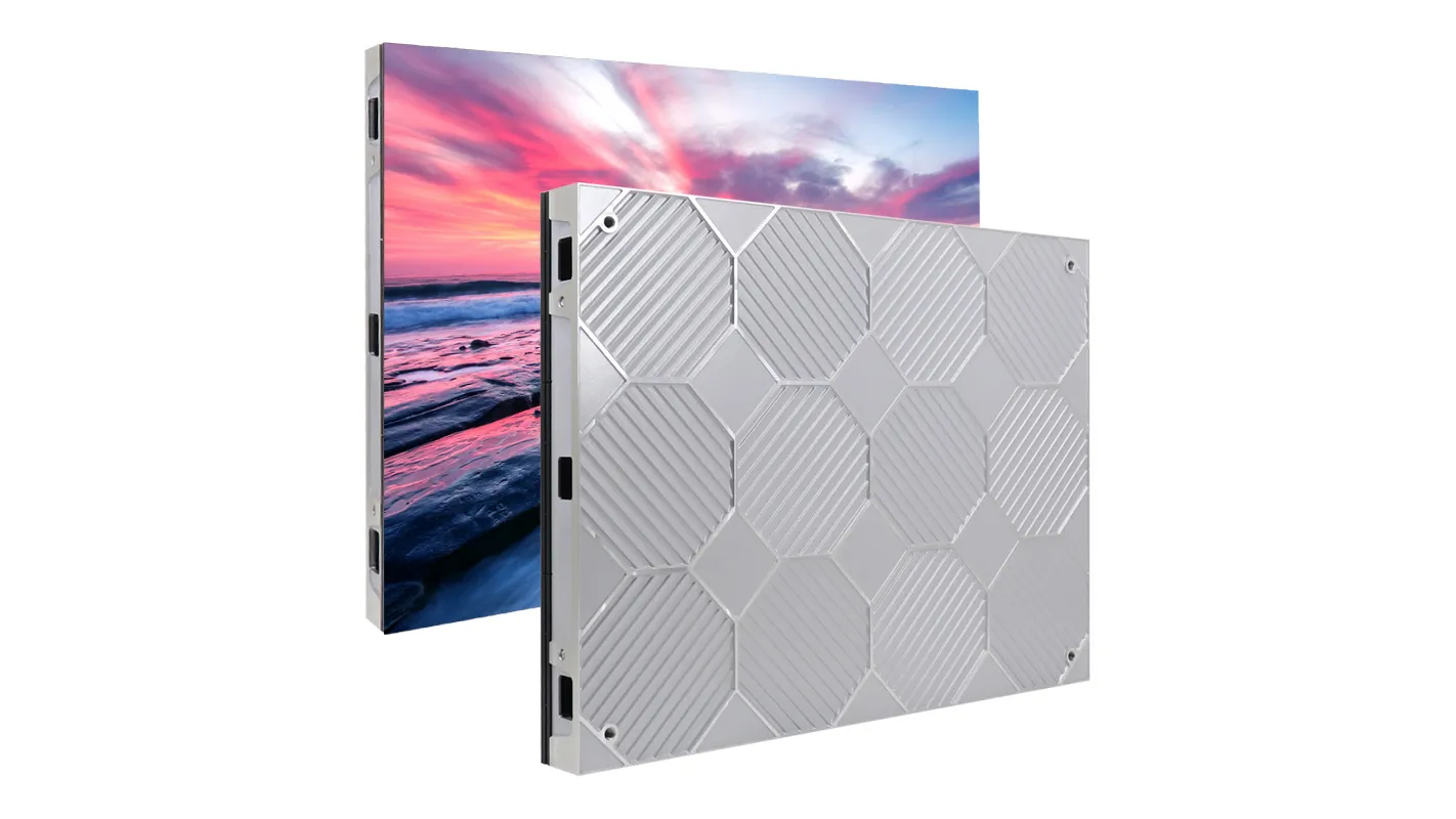
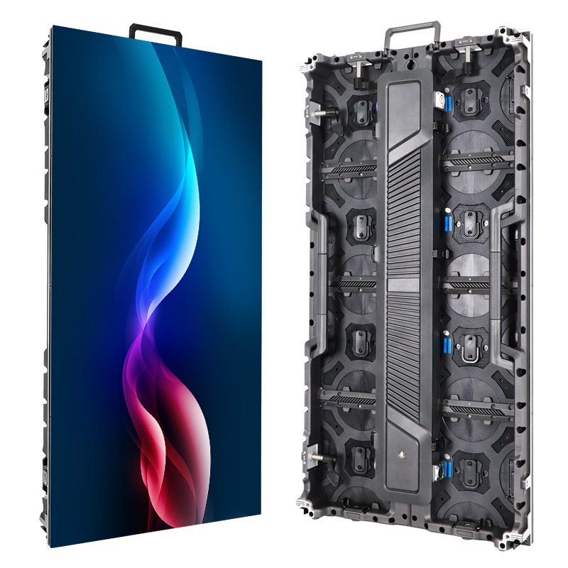
An LED module contains an array of light-emitting pixels and the circuitry needed to drive them. Multiple modules form a cabinet, and multiple cabinets form the display. This hierarchy helps narrow the investigation: a single affected subpixel suggests a different starting point from several cabinets failing together.
Most full-color pixels combine red, green, and blue emitters. Losing one color channel can make a pixel appear incorrectly colored rather than completely dark. Likewise, a module showing the wrong color may still have functional LEDs but be receiving incorrect data or operating with inappropriate settings.
01. Read the shape of the defect
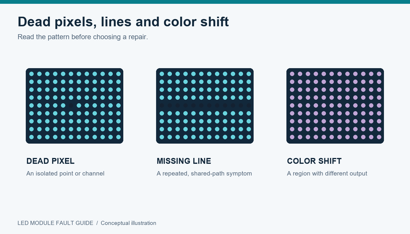
Begin by recording whether the problem affects one pixel, a repeated group, a complete row, one module, or a larger display region.
| Visible symptom | Possible causes | Useful first check |
|---|---|---|
| One pixel remains dark | LED package, solder joint, local circuit fault | Compare red, green, and blue test patterns |
| One pixel stays illuminated | Driver output, short circuit, LED-related fault | Display black and inspect the affected channels |
| A fixed row or column is missing | Shared drive circuit, connection, PCB trace | Determine whether the defect stops at the module edge |
| Several modules show corrupted images | Signal cable, receiving-card output, configuration | Map affected modules to their shared signal path |
| One module has a different tint | Calibration, LED characteristics, settings, power | Compare primary colors and neutral gray |
| A module flickers intermittently | Unstable power, poor connection, signal integrity | Record the operating conditions when flicker appears |
| A complete module is black | Missing power, missing data, hardware failure | Check its power and signal paths separately |
These are diagnostic starting points, not component-level verdicts. A reliable LED module fault report describes what the technician observed before proposing a repair.
Also establish when the symptom began. A fault following transport suggests a different investigation from one appearing immediately after a receiving-card configuration change.
2. How to Test an LED Module and Isolate the Fault
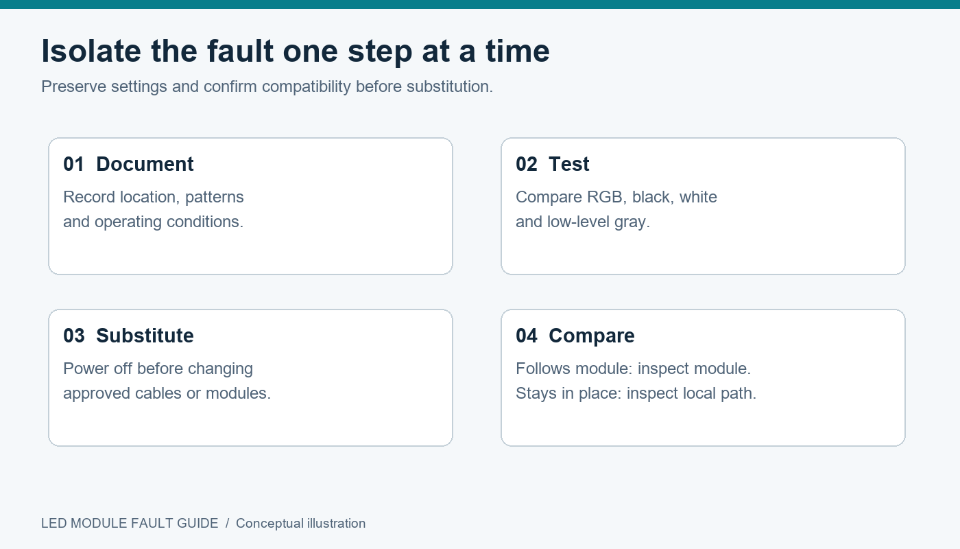
Effective LED module troubleshooting changes one variable at a time. Replacing a cable, loading a configuration, and adjusting brightness simultaneously may restore the picture, but it leaves the original cause unknown.
01. Document the screen before changing it
Photograph the entire display and the affected area. Record cabinet and module positions, product identifiers, controller settings, and whether the fault appears immediately or after warm-up.
Back up available receiving-card configuration files and calibration data before making changes. These serve different purposes: configuration defines how hardware operates, while calibration compensates for measured optical differences.
Use the manufacturer’s service procedure. De-energize equipment before disconnecting modules or internal cables unless the specific system explicitly supports that operation. Live electrical measurements should be performed by qualified personnel using appropriate equipment.
02. Use test patterns with a clear purpose
Moving video can hide defects. Static patterns make LED module faults easier to locate and compare.
| Test pattern | What it helps reveal | What to record |
|---|---|---|
| Full red | Missing or uneven red output | Isolated pixels versus repeated groups |
| Full green | Missing or uneven green output | Whether the same positions fail |
| Full blue | Missing or uneven blue output | Channel-specific defects |
| White within approved operating limits | Combined output and load-related symptoms | Tint, dim regions, instability |
| Black | Unwanted illumination or ghosting | Fixed bright points or faint repeated images |
| Low-level gray | Near-black nonuniformity and color shift | Whether defects disappear at higher levels |
| Grid or coordinate pattern | Mapping and image alignment | Repeated, displaced, or missing image sections |
Do not begin with prolonged maximum-output testing on a damaged or overheating cabinet. Use controlled conditions consistent with the product’s service instructions.
03. Separate source problems from display problems
Where supported, compare an internal display-system test pattern with the external video feed. If the internal pattern is correct while source content is wrong, investigate the source, processor, and input settings.
The test-pattern generation point matters. A pattern generated at a receiving card bypasses more upstream equipment than one generated at the processor.
04. Use controlled substitution
After confirming electrical and mechanical compatibility, substitute a known-good cable or module. Label components so that original locations remain traceable.
If the LED module fault follows the module to another compatible position, suspicion shifts toward the module. If it stays at the original position, investigate the local power feed, connector, hub board, receiving-card output, or settings. Intermittent faults may require repeated observation before this distinction is conclusive.
3. Dead vs. Stuck Pixels: Causes and Repair Options
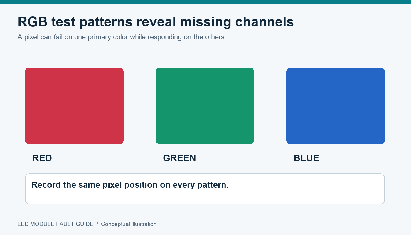
A dead pixel fails to produce expected light. A stuck pixel remains illuminated or fails to respond correctly to changing content. On an RGB LED display, either condition may involve only one color channel.
This distinction matters because a pixel that looks black on a red test pattern may operate normally on green and blue. Calling it a completely dead pixel would hide useful diagnostic information.
01. What causes dead pixels on LED displays?
Possible causes include damaged LED emitters, fractured solder joints, broken PCB connections, and faults in the associated drive circuitry. Mechanical impact, unsuitable handling, moisture damage, and electrical stress can contribute.
Inspect the affected area under suitable magnification. Look for displaced packages, cracked surfaces, damaged masks, contamination, or signs of previous repair. Avoid pressing on the display face as a diagnostic method; temporary changes under pressure do not establish a safe repair.
A cluster or regularly repeated pattern of failed pixels deserves particular attention. Several dark points may share a drive channel or circuit connection, so replacing individual LEDs without testing that shared path can waste time.
02. Can dead LED pixels be repaired?
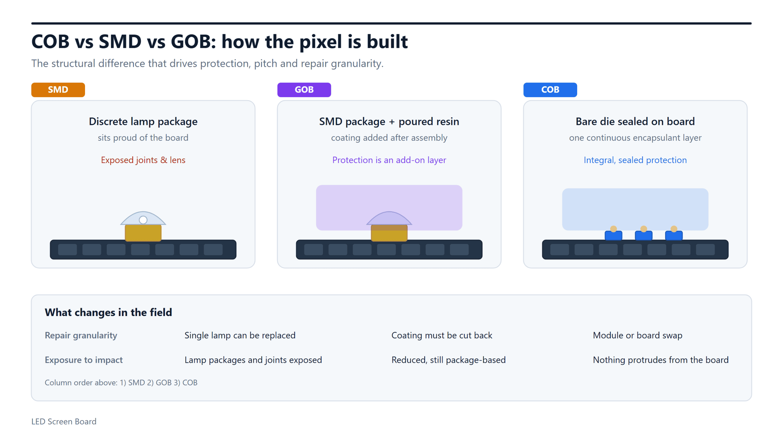
Some discrete SMD LED module designs support component-level repair by trained technicians. Successful work requires a compatible replacement package, correct orientation, controlled soldering, and inspection of the surrounding circuit.
COB and coated constructions may require specialized processes or manufacturer service. Accessing an emitter can damage encapsulation or protective layers, making ordinary field repair unsuitable.
Online “pixel-fixing” videos should not be treated as a remedy for failed direct-view LED hardware. Changing displayed colors cannot restore a broken solder joint or damaged semiconductor.
After LED module repair, test every primary color, black, white, and gray levels. Check neighboring pixels as well as the repaired point. Electrical function alone is insufficient: a replacement emitter may operate correctly while standing out because its brightness or color differs from the surrounding population.
4. Horizontal and Vertical Lines: Causes and Fixes
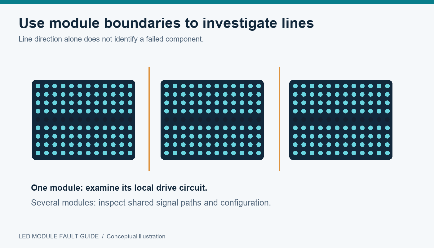
Horizontal or vertical lines often indicate a problem shared by multiple pixels. However, line direction alone cannot identify the failed component. Module layouts, scanning arrangements, and driver assignments differ.
The most useful distinction is whether the line remains within one module, repeats at regular intervals, or continues across several modules.
01. Lines confined to one module
A persistent line inside a single module may involve a driver output, row-selection circuit, solder joint, or PCB connection. Run primary-color patterns to determine whether all channels or only one channel are affected.
For example, a line missing only on green provides different evidence from a line that remains black on every pattern. A technician can relate that evidence to the module’s actual circuit arrangement.
02. Lines across multiple modules
When defects span several modules, inspect shared connections and signal distribution before assuming multiple independent hardware failures.
Check ribbon cables, hub connections, and receiving-card outputs against the cabinet documentation. Connector orientation and pin assignments must match; physical fit does not establish compatibility.
If the problem appeared after configuration changes, compare the active settings with the approved file for that hardware revision. Incorrect scanning or data settings can produce repeated blocks, displaced images, or line-like artifacts.
03. Intermittent lines and ghosting
Record whether lines appear with temperature changes, bright content, or movement of the cabinet. These relationships can help expose unstable connections, power problems, or marginal signal operation.
Faint unwanted illumination beside intended content may be ghosting rather than a permanently failed row. Driver timing and multiplexed operation can influence such artifacts; Texas Instruments discusses ghosting and low-grayscale behavior in its fine-pitch LED display technical article.
For a contractor, the practical rule is simple: preserve known-good settings and request hardware-specific guidance before experimenting with advanced timing parameters.
5. LED Module Color Shift: Calibration and Hardware Checks
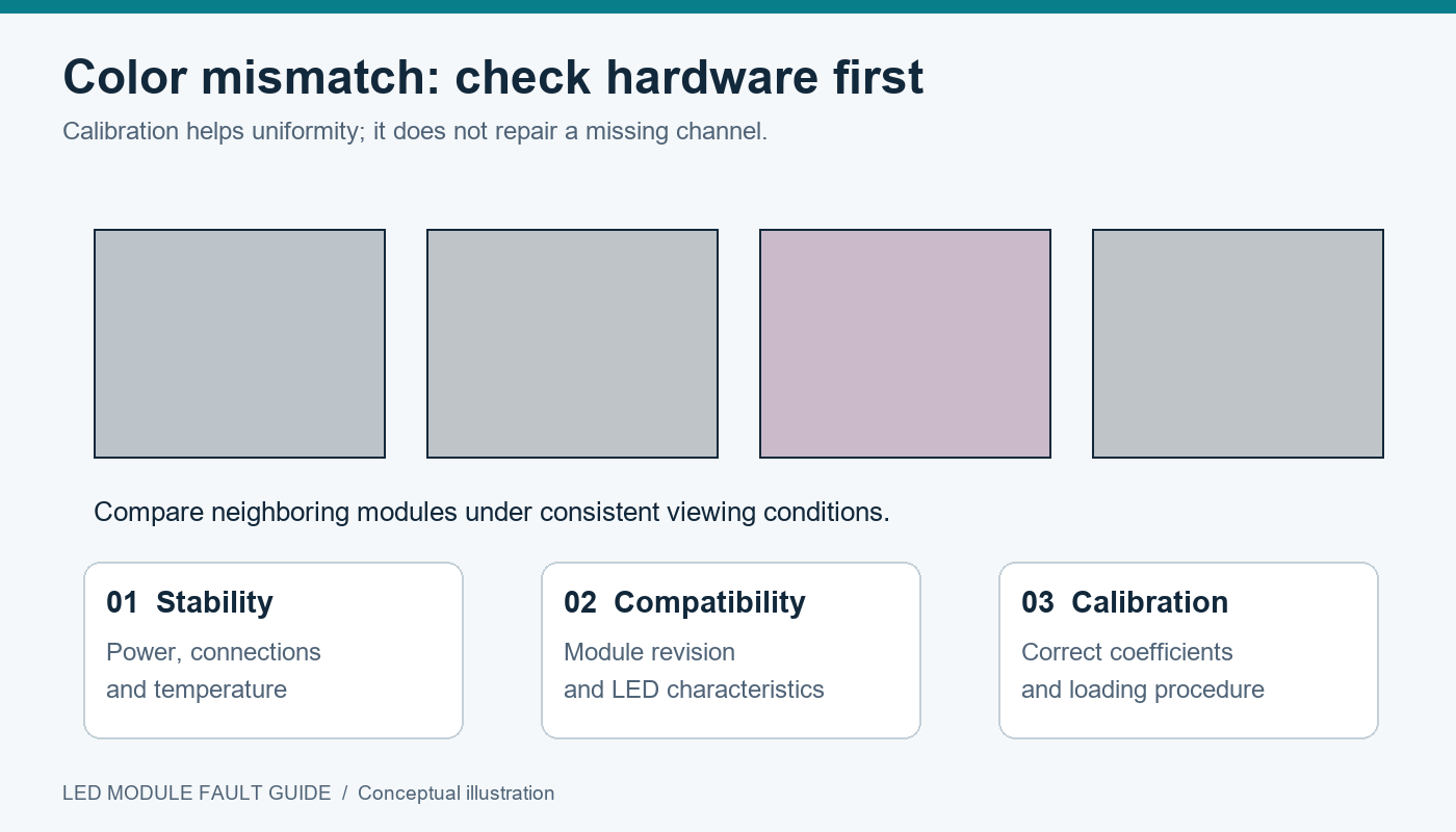
LED module color shift occurs when the displayed color differs from the intended output or from neighboring modules. It may appear as a tinted white area, an uneven gray background, or a mismatch that becomes visible only at particular brightness levels.
Start by separating localized mismatch from a screen-wide color change. One tinted module suggests a local issue. A whole screen changing appearance after a source adjustment calls for examination of the video and processing chain.
01. Identify when the mismatch appears
| Color-shift behavior | Areas to investigate | Appropriate next step |
|---|---|---|
| Replacement module differs from its neighbors | LED batch, operating history, calibration | Verify part compatibility and calibration procedure |
| Tint appears after receiving-card replacement | Configuration and calibration loading | Restore the approved files and coefficient handling |
| Color changes mainly near black | Grayscale processing and driver operation | Test gray ramps using the approved operating profile |
| Tint increases on brighter content | Power delivery, temperature, drive settings | Check operation under controlled load |
| Entire screen has incorrect colors | Source format, processor settings, global adjustments | Compare internal patterns with source content |
| Appearance changes strongly with viewing angle | Optical characteristics, alignment, surface condition | Compare modules from consistent viewing positions |
02. Confirm hardware stability before calibration
Calibration cannot repair a missing color channel, unstable connection, or damaged driver. Resolve these conditions first.
Power delivery also deserves attention. LED drivers require adequate electrical headroom to regulate current; insufficient supply conditions can affect output. Raising supply voltage without reference to the module specification is not an acceptable correction. Texas Instruments explains the underlying relationship in its RGB LED driver application report.
Compare modules after they have reached reasonably consistent operating conditions. Evaluating a newly powered spare beside a warm display can complicate the assessment.
03. Restore the correct calibration data
Calibration coefficients adjust output to improve uniformity. Depending on the system, data may reside in module memory, receiving cards, or external files.
Do not assume a replacement automatically uses the correct coefficients. For example, Daktronics documents a module-to-receiver calibration-loading procedure for a particular COB product family after receiver replacement. That procedure illustrates why calibration handling must follow the specific product documentation. See its commissioning and service procedure.
Calibration has limits. It cannot guarantee identical appearance across incompatible LEDs or restore output beyond a component’s capability. Matching an older screen may require reducing the brighter components’ output, with a corresponding limit on achievable uniform brightness.
6. LED Module Repair vs. Replacement: Costs and Limitations
Choosing between LED module repair and replacement requires more than comparing a repair quotation with a spare-part price. Include access labor, shipping, downtime, recalibration, and the risk of another service visit.
For an event rental company, immediate restoration may justify swapping a module and repairing it later. For a permanent installation with difficult access, a verified replacement may be preferable to an uncertain field repair.
| Option | Suitable circumstances | Main advantage | Main limitation |
|---|---|---|---|
| Repair individual components | Localized damage on a serviceable design | Retains most of the original module | Requires specialist skill and optical verification |
| Install a compatible spare | Downtime matters and a verified spare exists | Faster restoration at the display | Spare may require calibration or further matching |
| Send the module for factory assessment | Complex construction or unclear failure | Access to product-specific processes | Shipping and service turnaround |
| Replace a coordinated group | Individual matching is no longer practical | Potentially more consistent appearance | Larger scope and higher project cost |
A repair is more attractive when the defect is localized, the PCB is sound, and suitable components remain available. Replacement deserves stronger consideration when damage is extensive, failures recur, or protective construction cannot be reliably restored.
Do not use a universal percentage rule for repair economics. Local labor rates, screen accessibility, spare availability, and contractual downtime obligations vary too widely.
01. Define acceptance before authorizing work
Agree on how the repaired or replaced LED module will be checked. Include pixel response, line defects, gray-level uniformity, color matching, and stability during representative operation.
The viewing conditions should reflect the installation. A close-view corporate display and a distant outdoor sign may have different contractual acceptance criteria.
Record the repair date, module position, replacement identity, and test result. This creates a service history that helps distinguish an isolated defect from repeated damage caused elsewhere in the system.
7. How to Choose a Compatible Replacement LED Module
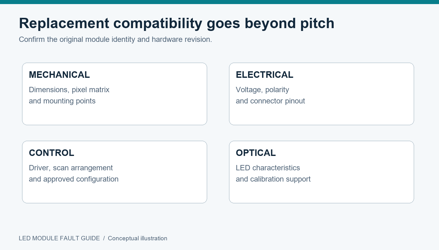
A replacement LED module must match more than pixel pitch. Two modules can share the same advertised pitch and dimensions while differing in electrical connections, scanning, driver hardware, or optical characteristics.
For distributors and procurement teams, purchasing by photograph alone creates avoidable risk. Obtain written compatibility confirmation tied to the original display and module revision.
| Compatibility item | What to confirm | Why it matters |
|---|---|---|
| Module identity | Model, revision, production information | Similar-looking versions may differ internally |
| Pixel pitch and resolution | Pixel spacing and exact pixel matrix | Determines physical and image alignment |
| Dimensions and mounting | Outline, holes, magnets, service orientation | Affects cabinet fit and safe retention |
| LED package and optical characteristics | Package type, brightness and color compatibility | Influences visible uniformity |
| Driver and scan configuration | Driver IC, scanning arrangement, approved settings | Determines correct image operation |
| Electrical requirements | Voltage rails, polarity, connector pinout | Prevents incompatibility and damage |
| Data interface | Connector definition and signal requirements | Enables correct communication |
| Protective construction | Coating, encapsulation, sealing requirements | Preserves suitability for the installation |
| Calibration support | Available coefficients and loading method | Supports matching after replacement |
Common-anode and common-cathode designs should not be treated as interchangeable. The replacement must follow the original electrical architecture and approved control configuration.
01. Send the supplier a useful identification package
Provide clear front and rear photographs, product labels, PCB revision markings, cabinet details, and available configuration files. Include the installation date and any previous component substitutions.
For an EagerLED project inquiry, use this package to request confirmation of the appropriate module, compatible spare strategy, and maintenance documentation. EagerLED’s LED display parts and tutorial library also provides a starting point for product-related maintenance resources.
Avoid assuming that an unspecified “equivalent” module will match after calibration. Ask what equivalence covers: mechanical fit, electrical operation, optical performance, or all three.
02. Plan spare inventory around operational needs
Set spare quantities according to display size, service access, shipping lead time, downtime tolerance, and the number of distinct module types. No single spare percentage suits every project.
Where possible, procure identified spares with the original display and periodically verify them. Matching production information helps, but stored spares and operating modules can still develop different optical characteristics over time.
8. Preventing LED Module Failures in Indoor and Outdoor Displays
Preventive maintenance should address the conditions that cause faults, rather than simply checking whether the screen turns on.
For indoor installations, focus on ventilation, contamination, connector condition, and safe service access. For outdoor LED displays, include enclosure condition, drainage, cable entries, corrosion, and environmental exposure.
01. Match maintenance to the application
| Application | Maintenance priority | Practical action |
|---|---|---|
| Indoor commercial display | Airflow and dust accumulation | Inspect ventilation and clean using approved methods |
| Outdoor fixed installation | Water entry and deteriorating seals | Inspect vulnerable entry points and enclosure condition |
| Rental and touring display | Handling damage and connector wear | Inspect before dispatch and after return |
| Fine-pitch control room | Near-black uniformity and visible pixel defects | Use documented gray-level and primary-color checks |
| Broadcast or camera-facing installation | Interaction between display and camera settings | Validate the complete camera-display operating setup |
Do not infer the protection of an assembled screen from a module rating alone. Cabinet construction, installation details, and serviced joints also affect environmental performance.
After outdoor LED module replacement, verify that gaskets, fasteners, and cable arrangements are restored according to the product instructions.
02. Keep operating settings controlled
Maintain a record of approved brightness, receiving-card configuration, firmware versions, and calibration procedures. Restrict undocumented changes, especially during urgent troubleshooting.
When an LED module fault repeatedly affects the same location, investigate the cabinet environment and infrastructure. Replacing the module repeatedly will not correct a poor power connection, local water entry, or inadequate airflow.
03. Inspect before faults become service calls
Schedule checks around the installation’s actual workload and exposure. Rental stock benefits from inspection between deployments; fixed displays need maintenance intervals suited to their surroundings and operating schedule.
Track defect location and recurrence. A growing cluster of pixel failures or repeated connector problems can justify deeper investigation before a major operational interruption.
9. FAQ
01. Are dead pixels covered by an LED display warranty?
Coverage depends on the sales agreement, defect criteria, warranty period, and identified cause. Do not assume that every failed pixel automatically qualifies for replacement. Before purchasing, ask how pixel defects are assessed, who pays service and transport costs, and whether unauthorized repair affects coverage. Retain dated fault photographs and module identifiers.
02. Can a phone camera create lines that are not visible in person?
Yes. Camera shutter timing can interact with LED scanning and brightness modulation, producing bands that are not apparent to the eye. Compare direct viewing with photographs taken using different shutter settings. A camera-only artifact does not automatically indicate an LED module fault, although camera-facing installations still require an appropriate system setup.
03. Will a higher refresh rate fix dead pixels or color shift?
A higher refresh rate cannot repair a failed emitter or broken connection. Changes to the operating profile may affect camera performance or grayscale behavior, but the available tradeoffs depend on the hardware. Use approved settings and judge the complete picture rather than selecting the highest advertised refresh-rate value.
04. How should spare LED modules be stored?
Use protective packaging that prevents mechanical damage and follow the manufacturer’s temperature, humidity, and electrostatic-handling instructions. Label spares by model and revision, and keep their related configuration information accessible. Avoid treating a loose module as a general electronic part: its display surface, connectors, and optical components require protection.
05. Can indoor LED modules replace outdoor modules temporarily?
Only if the manufacturer confirms suitability for the complete application, which should never be assumed. A physically fitting indoor module may lack the required protection or optical performance. Temporary installation does not remove exposure to moisture, contamination, or electrical incompatibility. Use an approved replacement or isolate the affected area according to the service procedure.
06. What evidence should accompany an LED module warranty claim?
Provide the order or product reference, module identifiers, cabinet position, and clear images of the defect. Include results from primary-color and gray-pattern tests, when the fault started, and any recent maintenance or configuration changes. Describe controlled substitutions already performed, and preserve the original component for assessment when requested.
07. Does firmware need updating after an LED module replacement?
Not automatically. A like-for-like module may operate with the existing approved configuration, while a changed hardware revision may require different support. Ask the supplier to confirm compatibility before updating. Preserve working files and follow the documented update sequence, since an unnecessary firmware change can complicate otherwise straightforward troubleshooting.
08. Can a display keep operating with one faulty LED module?
That depends on the failure. An isolated visual defect may permit temporary operation under the site’s acceptance rules. Overheating, damaged wiring, water ingress, or unstable electrical behavior requires a different response and should be assessed before continued use. Operational urgency should not substitute for identifying the nature of the fault.
10. Conclusion
Dead pixels, persistent lines, and color shift become easier to resolve when the investigation follows the display’s physical and electrical structure. Document the symptom, use targeted test patterns, isolate power and signal paths, and confirm the fault before authorizing LED module repair or replacement.
For professional buyers, maintenance readiness starts during procurement. Compatible spares, accessible configuration files, clear calibration procedures, and defined acceptance criteria make future service more predictable. When planning an EagerLED installation or requesting replacement modules, provide the original hardware details and operating requirements so compatibility can be assessed accurately.
A successful LED module fault repair restores more than illumination. It returns the display to stable operation with acceptable image uniformity—and leaves enough documentation to make the next service decision faster.
 EagerLED Celebrates 2026 Mid-Autumn Festival with LED Screen