
An LED module scan rate of 1/8, 1/16 or 1/32 describes how many scan positions share a driver output over time. With otherwise comparable timing, a 1/8 scan LED module gives each position a larger share of the available cycle than a 1/16 or 1/32 design. That difference creates design tradeoffs; it does not establish a universal ranking of finished displays.
For a buyer comparing quotations, the useful question is whether the complete module can deliver the required brightness, shadow detail and camera performance within its approved operating limits. Two cabinets with the same pixel pitch and headline refresh rate can use different LED display scanning methods and require different receiving-card configurations.
This guide compares the three scan ratios for LED display buyers, distributors, AV integrators and project contractors. It explains the underlying timing, separates theoretical comparisons from product specifications, and turns the differences into practical sample tests and purchasing questions.
1. What Does LED Module Scan Rate Mean?
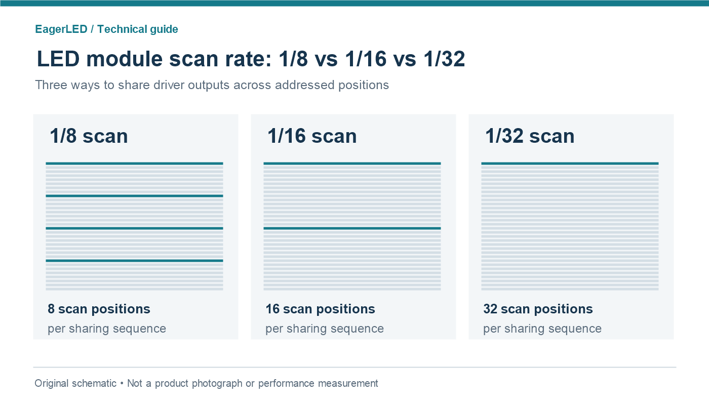
In multiplexed LED displays, a driver channel serves several LED positions in sequence. The notation 1/N scan identifies N scan positions in that sharing arrangement. A 1/16 scan LED module therefore has sixteen addressed positions per scan sequence in each applicable group. Multiple groups can operate in parallel, so this does not mean that only one physical row across an entire cabinet is illuminated.
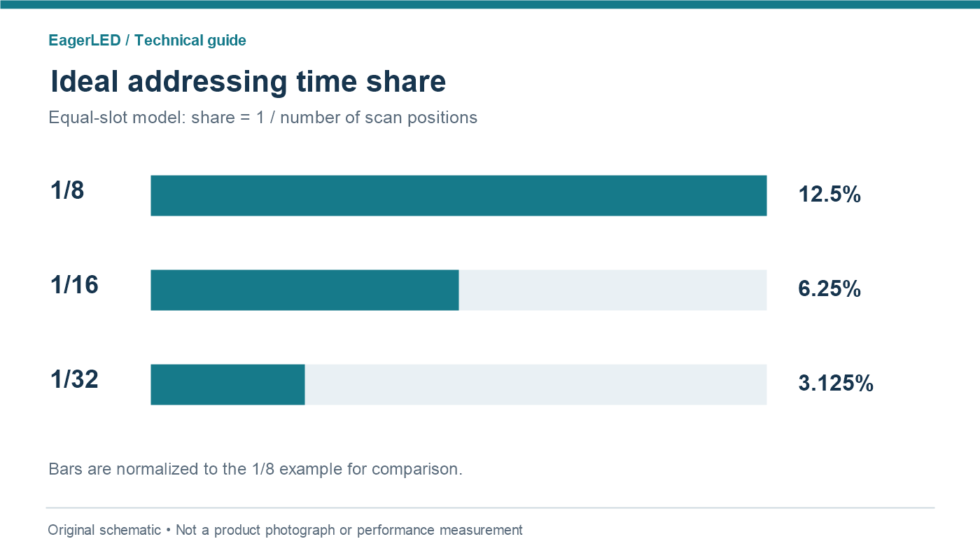
For an ideal equal-slot sequence, the nominal share of addressing time is 1/N. It is 12.5% for 1/8, 6.25% for 1/16 and 3.125% for 1/32. These percentages describe a simplified timing allocation. Actual light emission also depends on PWM, blanking intervals, current settings and the displayed pixel values.
The phrase LED display scan rate is widely used for this ratio, although it is not a frequency in hertz. To avoid ambiguity in a specification, write both the ratio and the refresh frequency in separate fields. Also avoid saying simply “higher scan”: a larger denominator means more multiplexing, while a larger fraction means a greater nominal duty share.
Some documentation expresses the same sharing concept as 8:1, 16:1 or 32:1 multiplexing. Confirm the manufacturer’s convention before comparing values. Brompton’s explanation of scan multiplexing describes the driver-output sharing behind this terminology.
2. How LED Display Scanning Methods Work
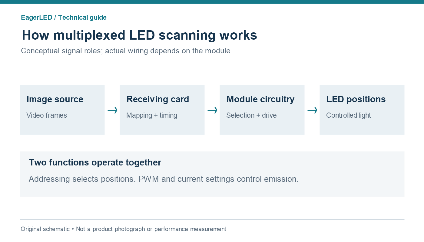
A complete display system must distribute image data, select the appropriate LED positions and control their emitted light. Those functions interact, but they are not interchangeable. The receiving card, module wiring, line-selection circuitry and driver IC together determine which pixels respond to each timing sequence.
01. Row selection and parallel data groups
Consider a simplified 32-row region with two independently driven groups. Each group could address sixteen positions, producing a 1/16 arrangement. Another architecture could divide those rows differently. The visible dimensions alone cannot tell you the LED module scan mode: the electrical grouping is what matters.
During transitions, outputs may be blanked while data and row selection settle. A design must manage those transitions to prevent unintended light. Therefore, drawing one continuous rectangular pulse per row is useful for explaining the principle but incomplete as a description of a working module.
02. PWM and the driver IC
Pulse-width modulation controls how light is distributed within available emission opportunities. Some drivers use memory and segmented PWM sequences rather than a simple once-per-frame sweep. Texas Instruments’ TLC5958 multiplexing application note illustrates one implementation with multiple subperiods. That architecture is an example, not a claim about the IC fitted to a particular EagerLED module.
This is why changing a software menu does not redesign a 1/32 scan LED module into a 1/8 product. A setting must describe the existing hardware correctly. Procurement should specify the supplied configuration and firmware alongside the LED scan ratio, rather than treating scan mode as an unrestricted user adjustment.
3. 1/8 vs 1/16 vs 1/32: LED Scan Rate Comparison
The most useful LED scan rate comparison separates mathematical facts from engineering tendencies. The time shares below follow directly from the ratios. Cost, brightness, refresh and reliability require evidence from the actual finished design.
| Comparison | 1/8 scan | 1/16 scan | 1/32 scan |
|---|---|---|---|
| Positions per sharing sequence | 8 | 16 | 32 |
| Ideal equal-slot time share | 12.5% | 6.25% | 3.125% |
| Sharing of driver outputs | Less than the other two | Intermediate | More than the other two |
| Potential design advantage | More time per position at equal cycle duration | Compromise between sharing and time allocation | Greater output sharing can help integration |
| Engineering issue to examine | Driver resources, PCB space and cost | Balance of image performance and implementation | Timing margin, current limits and low-gray behavior |
| Not established by the ratio | Finished-screen nits, watts, refresh frequency, camera compatibility, lifetime or selling price | ||
A 1/8 scan LED module can be attractive when a project benefits from less multiplexing and the additional hardware resources are justified. That does not excuse checking LED quality, calibration, thermal design or serviceability. A poorly configured lower-denominator product can still fail an acceptance test.
A 1/16 scan LED module provides a different allocation of those resources. It is worth evaluating when the supplier can demonstrate the required performance at the intended operating brightness. “Balanced” is a description of a design choice, not a certification or a guarantee of suitability.
A 1/32 scan LED module uses more sharing. It should not be dismissed solely because of its denominator, nor accepted solely because it is less expensive. Ask what driver architecture, timing and current limits support its specification. The relevant purchasing result is a compliant module at a justified total cost.
When comparing bids, keep module resolution, LED package, calibration state and operating target comparable. If those change together with the LED module scan mode, label the comparison as one between complete products. It cannot isolate the effect of scanning alone.
4. How Scan Ratio Affects Brightness and Power
A smaller denominator gives a pixel more nominal time to emit within an otherwise equal multiplex cycle. This creates brightness headroom. It does not prove that one commercial module will deliver twice the luminance of another, because the LEDs, current, PWM settings, optics and thermal operating point may differ.
01. Use duty-cycle calculations carefully
For a simplified rectangular-current model, average LED current equals on-state current multiplied by effective emission duty. If on-state current is 16 mA and effective duty is exactly 1/16, average current is 1 mA. At exactly 1/8 it would be 2 mA. This is arithmetic for an illustrative model, not an approved operating setting or a brightness prediction.
Real effective duty can be lower than the nominal scan share because of blanking and dimming. LED light output also does not remain perfectly proportional to current across all operating conditions. Never compensate for a larger scan denominator by multiplying current without checking the LED, driver and module specifications.
02. Compare power at an equivalent viewing target
For a useful power comparison, request measurements at the same calibrated luminance, white point, image pattern and ambient conditions. Record both the test pattern and the measurement location. Comparing a bright full-white test on one screen with typical video on another answers no useful efficiency question.
| Reported item | Required context | Why it matters |
|---|---|---|
| Calibrated luminance | White point, calibration, brightness setting and test pattern | Shows usable output in the intended setup |
| Maximum power | Specified worst-case pattern and operating conditions | Supports electrical and thermal planning |
| Typical content power | Identified content sequence and target luminance | Makes operational comparisons repeatable |
| Module temperature | Ambient, warm-up period and measurement point | Prevents a cold sample from representing steady operation |
The LED scan ratio alone also cannot establish service life. Ask for the product’s operating envelope and warranty terms rather than extrapolating lifetime from duty cycle. For a distributor, a repeatable production specification is more valuable than a theoretical claim that cannot be verified when replacement stock arrives.
5. Scan Rate vs Refresh Rate and Grayscale
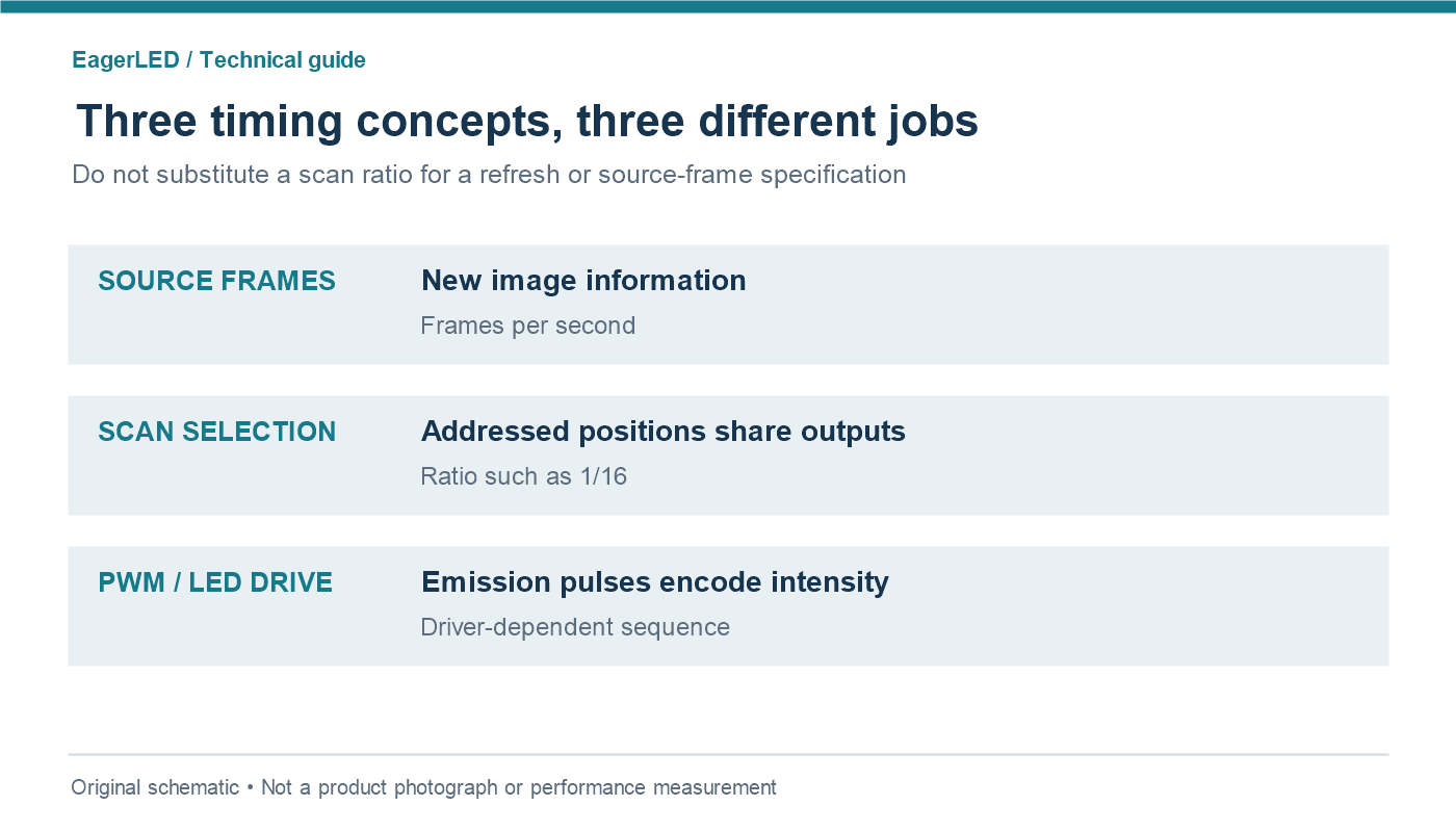
LED display scan rate, refresh rate and source frame rate describe different aspects of operation. Keep them separate in technical discussions, especially when several people contribute to the same quotation. A processor’s input-frame specification does not automatically describe the module’s light-output timing.
| Term | What to record | What it does not tell you |
|---|---|---|
| LED scan ratio | Multiplex sharing, such as 1/16 | The finished display’s refresh frequency |
| Refresh rate | Specified LED-drive repetition frequency and test conditions | The number of unique source frames |
| Source frame rate | Incoming video frames per second | The complete PWM or scan sequence |
| Grayscale | Usable intensity gradation at the chosen configuration | Guaranteed visible shadow detail from a bit-depth label |
Refresh and grayscale performance depend on timing budgets, driver capabilities and configuration. For example, the TLC5958 product documentation describes PWM grayscale control and display memory alongside support for multiplexing up to 32 positions. Their coexistence shows why “1/32” is not itself a refresh-rate specification.
Do not divide an advertised refresh value by the scan denominator and present the result as a universal effective refresh rate. Manufacturers may describe different aspects of their drive sequence, and segmented PWM changes the relationship between an individual pulse, a scan sequence and a complete grayscale period.
During evaluation, show smooth dark ramps and near-black neutral images at the actual operating brightness. Look for lost shadow steps, color shifts and unstable pixels. Keep the test content unchanged while recording each approved configuration. A higher headline number is not an improvement if useful gradation disappears.
The NovaLCT configuration manual documents distinct performance settings, including refresh, grayscale and clock parameters. Follow the documentation for the actual hardware and software version. For the broader timing vocabulary, see our LED refresh rate guide.
6. Scan Ratio and Camera Banding: What to Test
A wall can look acceptable to an audience and still show bands on a recording. Cameras collect light during finite exposure intervals. If those intervals sample the multiplexed emission unevenly, different portions of the picture can receive different amounts of light. A rolling shutter adds another timing relationship because sensor rows are not all exposed simultaneously.
For a camera-led project, lower multiplexing can provide useful design margin, but the LED display scan rate is only one variable. Test the exact panel, receiving system, firmware, camera mode, shutter setting and brightness combination. Neither a 1/8 label nor a high refresh specification replaces that test.
Brompton’s ShutterSync documentation explains how supported systems tune LED timing for camera exposure and use Genlock. Treat such features as system-specific capabilities. Do not assume they are available on every receiver or solve every artifact.
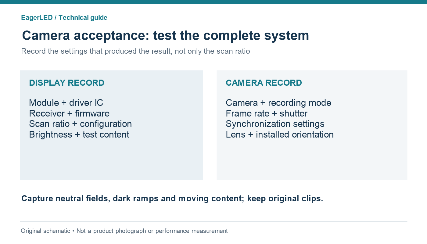
Start with the production settings the camera team expects to use. Capture neutral fields, dark gradients and moving content. Include the planned high-frame-rate or short-exposure modes if they are part of the job. Keep the original clips with the settings log, rather than approving the panel from a compressed sales video.
Distinguish temporal bands from moiré, focus issues and content artifacts. Moiré involves spatial interaction between image sampling and the LED pixel structure; changing the LED scan ratio alone is not a general cure. When a sample fails, document the symptom before changing several settings at once, so the successful configuration can be reproduced.
7. Choosing a Scan Mode for Your LED Display Project
Choose the LED module scan mode after defining the viewing task. Start with installation conditions, viewing distance, content, operating luminance and camera use. Then compare the modules that meet those conditions. Selecting a denominator first can exclude a suitable product or distract from a more important limitation.
| Project | Priority | Acceptance evidence |
|---|---|---|
| Indoor corporate or retail wall | Comfortable output, readable content and smooth dimming | Inspection at normal room light and operating brightness |
| Outdoor advertising | Required luminance, thermal stability and environmental suitability | Calibrated output and power records under stated conditions |
| Rental stage with live cameras | Repeatable camera behavior and fast service | Camera clips, approved presets and compatible spare modules |
| Broadcast or virtual production | Exposure compatibility, shadow detail and synchronization | Tests with production cameras, lenses and intended frame modes |
For indoor installations without demanding camera requirements, evaluate a 1/16 scan LED module and a 1/32 scan LED module on visible performance and lifecycle support. Avoid paying for an architectural preference that produces no demonstrated benefit in the intended installation.
For camera-critical work, include a 1/8 scan LED module in the comparison when a suitable product is available. Ask the integrator to document the benefit under the required camera settings. Any premium should be tied to a tested result, an operating margin or a support requirement, rather than an unsupported claim that every other ratio is unsuitable.
Distributors should also consider batch consistency and replacement availability. A slightly different module that fits the same cabinet can complicate configuration and calibration. Project contractors need the accepted hardware revision recorded in the handover documents so later service does not depend on memory or an old sales listing.
8. How to Verify Scan Mode Before Buying LED Modules
Ask the supplier to identify the LED scan ratio in writing for the exact module revision. Cross-check the specification with its configuration file and a working sample. If those disagree, resolve the discrepancy before accepting a batch. A connector photograph or pixel-pitch label is not sufficient evidence of the internal addressing scheme.
01. Build a configuration record
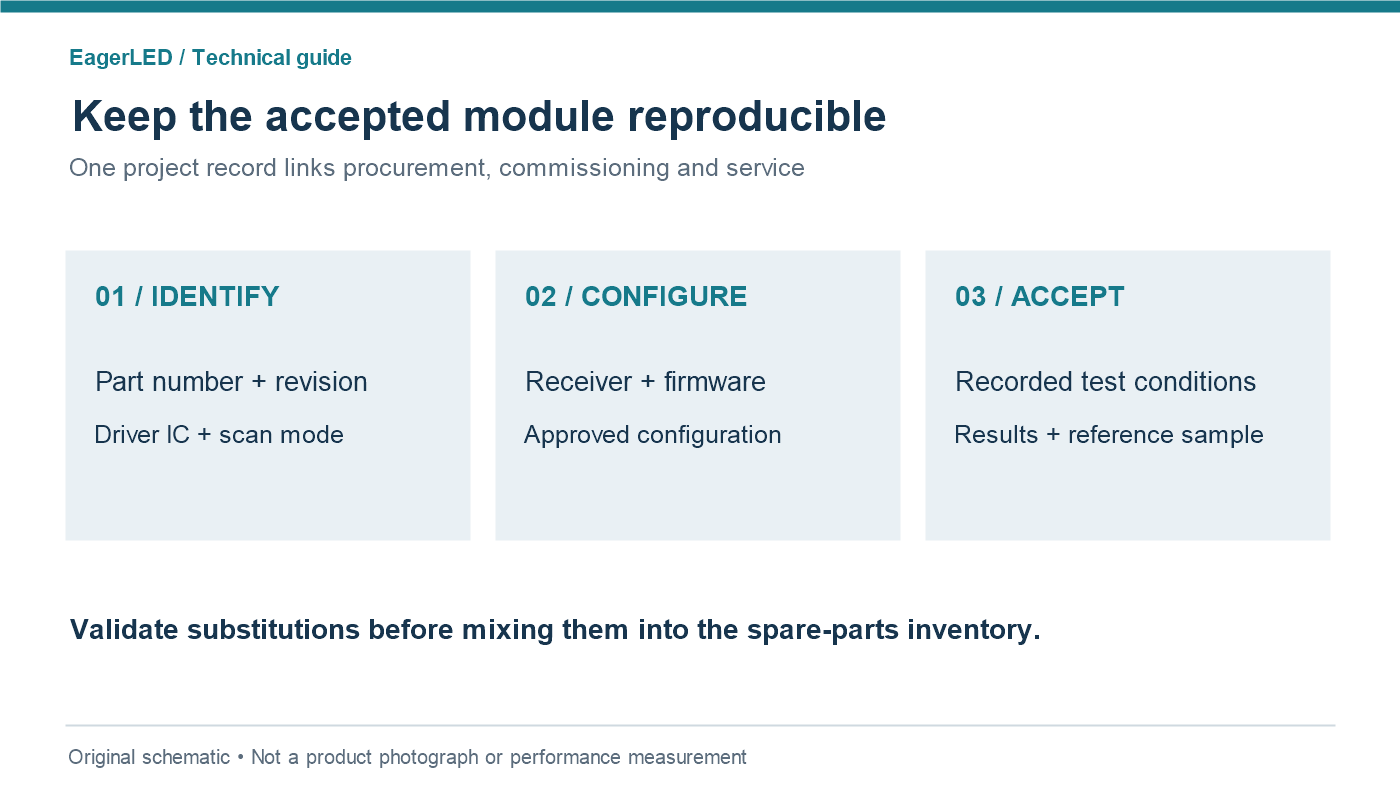
Record module part number, PCB revision, resolution, driver IC, scan mode, connector mapping, receiving-card model, firmware and configuration-file version. Preserve the original working file before commissioning changes. The record should make it possible for another technician to restore the approved arrangement without experimenting on an installed wall.
Use our receiving-card wiring checklist to organize the physical inspection. Qualified personnel should isolate power before altering wiring. Match the supplied interface documentation rather than assuming that similar-looking connectors use identical signals.
02. Require a repeatable sample acceptance test
Agree on pass criteria before the supplier demonstrates the sample. Use your own representative content as well as diagnostic patterns, and record the exact settings. Separate a failed setup from a failed specification: the supplier may correct a configuration error, but the final approved settings must accompany production units.
- Verify pixel mapping and color order with identifiable patterns.
- Inspect low-gray transitions and uniform fields at operating brightness.
- Measure luminance and power under agreed, documented conditions.
- Run camera tests when recording is part of the application.
- Confirm a replacement module works with the approved configuration.
A complete quotation should identify included calibration, configuration delivery, spares, support and exclusions. Use our LED display module supplier checklist to structure the commercial discussion. Requesting an EagerLED proposal with these inputs lets the comparison focus on a defined project rather than an isolated scan specification.
For a multi-batch order, nominate an accepted reference sample and keep its identification with the purchase record. Require written notice of changes to the driver IC, PCB or LED module scan mode. A substitute may be usable, but it should go through compatibility and acceptance checks before entering the same spare-parts pool.
9. FAQ
01. Does 1/32 scan mean the module has 32 pixel rows?
No. It describes the multiplex sharing arrangement, not the total physical height. A module may have several parallel data groups or an addressing layout that is not obvious from its dimensions. Confirm the module resolution and LED scan ratio separately in the supplier’s documentation.
02. Can modules with different scan modes share one cabinet?
Do not assume they can. Independent outputs and supported configurations may accommodate some combinations, but mapping, timing, calibration and service complexity must be evaluated. For a normal replacement, use the approved matching module unless the supplier validates the alternative in that exact cabinet.
03. Can a phone video identify the LED display scan rate?
A phone clip can reveal an artifact worth investigating, but it cannot reliably identify the scan ratio. Automatic exposure, sensor readout and video processing can change what appears. Use module documentation and configuration evidence to identify the ratio; use a controlled camera test to evaluate performance.
04. Does SMD, GOB or COB packaging determine the scan ratio?
No. Packaging and protective construction describe different design choices from electrical multiplexing. Do not infer LED module scan mode from a packaging label. Ask for the actual scan specification, driver information and operating test results for the product being quoted.
05. Can I replace a module using only its pitch and dimensions?
No. Those identify spatial and mechanical characteristics but not complete compatibility. Check scan mode, driver IC, voltage, pin mapping, revision and calibration requirements. Our LED module fault guide helps separate replacement compatibility questions from faults elsewhere in the display.
06. Will rotating a cabinet change its scan mode?
Rotation does not rewire the module or change its underlying ratio. It can change the apparent direction of artifacts relative to the camera sensor. Confirm that the controller supports the required image mapping, then test the installed orientation instead of relying only on a sample tested upright.
07. Is a larger scan denominator proof of lower quality?
No. It identifies more sharing, not a quality grade. Assess the delivered image, approved operating limits, manufacturing consistency and support. A 1/32 scan LED module that meets the project criteria can be a better purchase than another module whose theoretical advantages are not delivered in practice.
08. What should I do if two suppliers use different scan notation?
Ask each to state how many positions share one driver output and provide the corresponding configuration. Record both their original notation and your normalized description. Do not compare “8 scan” with “1/8 scan” until the manufacturer confirms that the terms describe the same arrangement.
10. Conclusion
The practical difference between 1/8, 1/16 and 1/32 is how a module shares driver resources and allocates addressing time. LED module scan rate influences engineering options, but it does not independently specify brightness, refresh, camera compatibility or lifetime.
Use an LED scan rate comparison to ask better questions: what hardware is supplied, under which conditions is performance specified, and can the sample reproduce the required result? Keep the accepted configuration and evidence with the order. For your EagerLED project brief, include installation conditions, target brightness, camera settings and replacement needs so the proposed module can be judged against the work it must actually perform.
 LED Transparent Film Screen: Glass Retrofit Checklist