
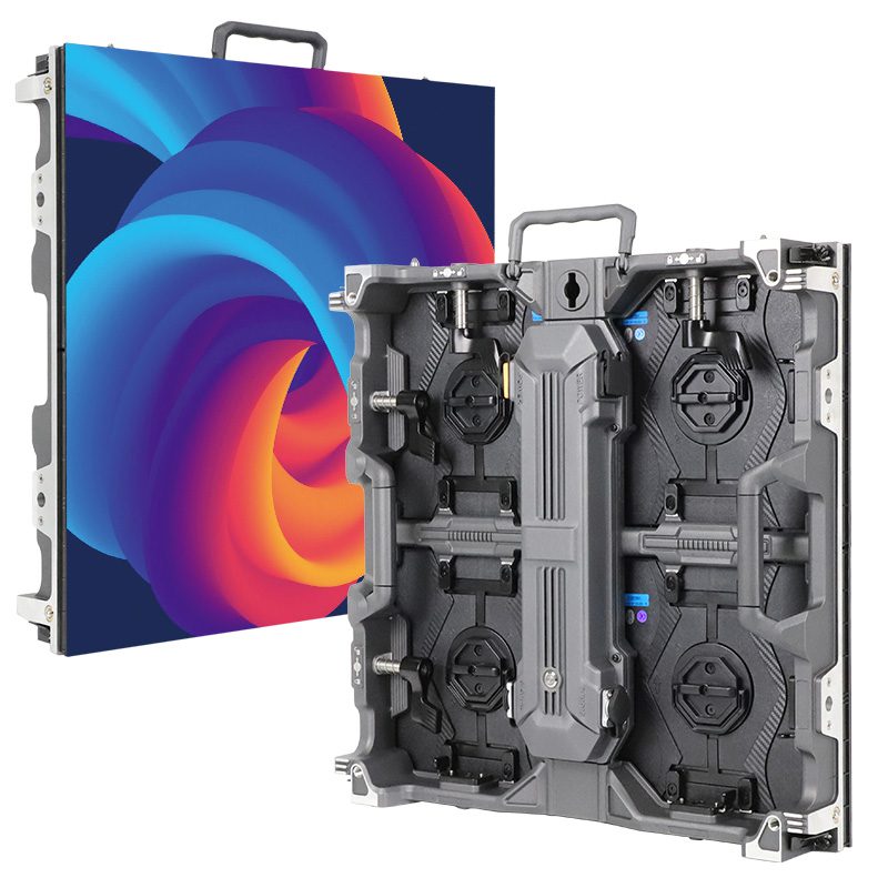
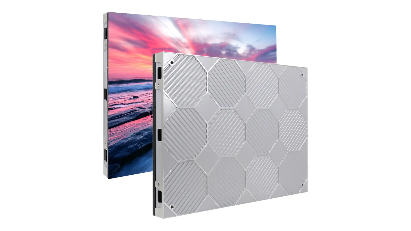
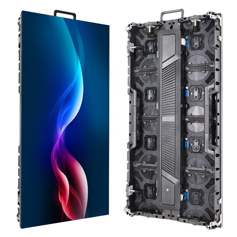
A fine-pitch LED display is a long-term service commitment as well as an image-quality purchase. Buyers need to know how the screen performs when new, but distributors and AV integrators also need a practical answer to a less visible question: what happens when a component fails after installation? MIP LED packaging deserves attention because it influences both module construction and the available repair methods.
MIP generally means Micro LED in Package. Small LED chips are integrated into discrete packages before those packages are assembled onto a display module. This creates opportunities for package-level testing, sorting, and replacement. However, a replaceable component does not automatically mean a quick or economical field repair.
For professional buyers, the useful comparison goes beyond MIP versus COB or conventional SMD. Package dimensions, PCB design, surface protection, spare-part availability, and calibration support all affect whether a damaged module can return to service with an acceptable appearance.
This guide explains how MIP LED packaging affects module design and repairability, what to verify in a supplier proposal, and how to evaluate the technology for an EagerLED project inquiry without relying on unsupported performance claims.
1. What Is MIP LED Packaging, and How Does It Work?
MIP LED packaging places small LED chips inside discrete components that are subsequently mounted onto a display circuit board. The package is an intermediate building block between the LED chip and the finished module.
Terminology can vary between manufacturers. Buyers should request the actual package construction and part number rather than assume that every product carrying the MIP label has identical characteristics.
01. Micro LED in Package: From LED Chips to Components
The packaging stage establishes the component’s electrical connections, physical dimensions, and optical interface. Depending on the design, an individual component may contain a particular RGB or pixel arrangement.
Package-level inspection and sorting can occur before module assembly. Kinglight describes bin classification and the arrangement of its MIP devices into modules as features of its manufacturing approach. These are manufacturer-specific capabilities, rather than a guarantee of performance for every MIP display. Kinglight’s MIP technology overview
02. How MIP Packages Become LED Display Modules
During module assembly, the selected packages are positioned and connected to a PCB using the specified mounting process. Driver electronics, connectors, mechanical supports, and any additional surface protection complete the module design.
Several modules then form a cabinet or another display assembly. Cabinet alignment, power distribution, receiving cards, and system configuration influence the finished screen.
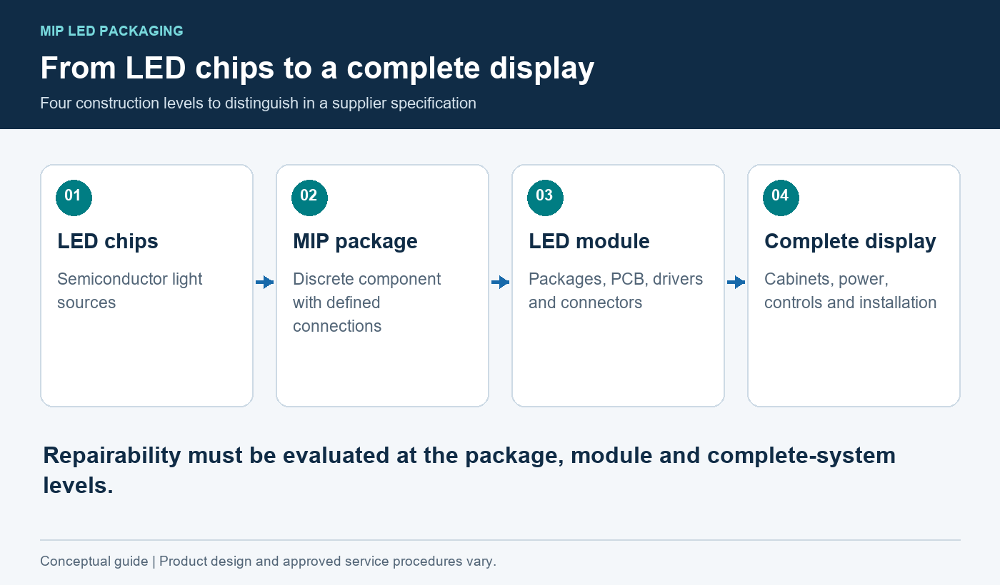
For purchasing purposes, distinguish four levels:
| Level | What it describes | Why buyers should distinguish it |
|---|---|---|
| LED chip | The semiconductor light source | Chip characteristics alone do not define display performance |
| MIP package | Chips and connections within a discrete component | Establishes the component footprint and replacement requirements |
| LED module | Packages, PCB, drivers, and associated construction | Determines practical electrical and mechanical compatibility |
| Complete display | Modules, cabinets, power, controls, and installation | Determines the customer’s operating and maintenance experience |
A package specification is therefore only one part of a complete MIP LED display specification.
2. How MIP Packaging Shapes LED Module Design
MIP LED packaging affects component placement and access, but the display manufacturer still makes important decisions about the PCB, driving arrangement, and mechanical structure.
01. Package Size, Pixel Pitch, and PCB Layout
Pixel pitch is the center-to-center distance between adjacent pixels. Package size influences the space available for achieving that pitch, but the two measurements are not interchangeable.
The PCB must accommodate connection pads, routing, electrical clearances, and assembly tolerances. As the layout becomes denser, inspection and rework access may become more demanding.
Ask for both the module drawing and the package information. A nominal pitch value does not reveal pad geometry, package orientation, or the clearance available around a failed component.
02. Driver Configuration, Power Delivery, and Heat Management
A MIP LED module also depends on its driver ICs, scan arrangement, power distribution, and operating settings. These influence grayscale behavior, electrical loading, and thermal conditions.
MIP LED packaging does not independently determine refresh rate, power consumption, or camera performance. Those claims should be supported by data for the complete proposed configuration.
Similarly, thermal performance depends on the entire heat path. Request operating limits and test conditions for the finished assembly instead of assuming that a smaller package necessarily produces a cooler screen.
03. Surface Protection and Access for Servicing
A protective treatment can change how technicians reach the packages. Some MIP LED modules may use additional encapsulation or coatings; the exact construction must be confirmed.
Protection can be useful during handling, but removing and restoring it may complicate component replacement. Front-service access also needs clarification: it often describes how a module is removed from a cabinet, rather than how individual packages are repaired.
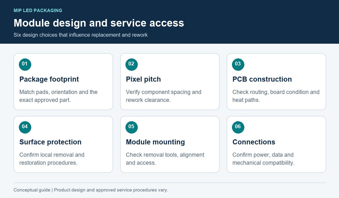
| Design choice | Effect on module engineering | Repairability question |
|---|---|---|
| Package footprint | Defines pad arrangement and placement requirements | Is the exact replacement package available? |
| Pixel pitch | Influences component spacing and routing density | Can a package be removed without disturbing neighbors? |
| PCB construction | Affects routing, mechanical behavior, and heat distribution | What inspection is required after rework? |
| Surface coating | Changes protection and optical appearance | Can it be restored consistently after repair? |
| Module mounting | Determines removal and alignment procedures | Can technicians exchange the module safely and accurately? |
| Connector arrangement | Affects service access and replacement compatibility | Are connections accessible without stressing the board? |
3. How Testing and Calibration Affect MIP Display Quality
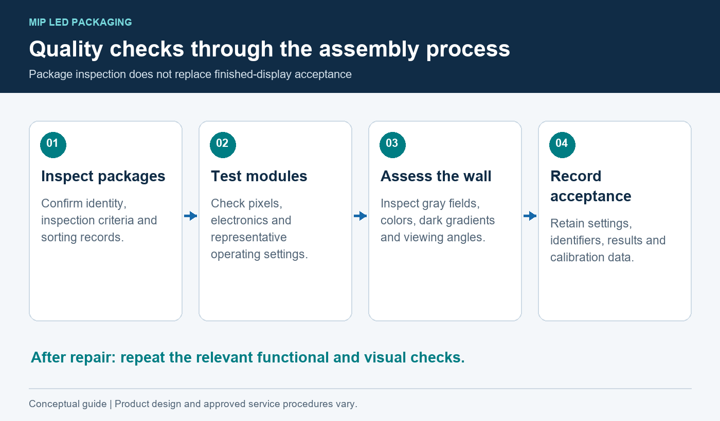
Testing should follow the product through assembly. A package that passes inspection can still encounter soldering, handling, or configuration problems later.
01. Package Inspection, Sorting, and Color Consistency
Sorting groups components according to defined characteristics. For MIP LED packaging, buyers should ask which optical and electrical criteria the supplier controls and how those records connect to the module production batch.
Avoid treating “tested packages” as equivalent to “uniform finished screen.” Assembly conditions, drive settings, surface appearance, and viewing angle can still affect the result.
Nationstar’s product information illustrates why checking the particular device matters: its MIP-IMD range includes construction descriptions such as surface-mount devices, black frames, and flip-chip packaging. The category name does not replace the individual specification. Nationstar’s MIP-IMD product information
02. Module Assembly and Finished-Display Testing
Inspect representative MIP LED modules individually and within an assembled cabinet. Then assess several cabinets together where the project scale makes this practical.
Useful test content includes white fields, primary colors, neutral gray, dark gradients, fine text, and representative customer material. Look for defective pixels, module boundaries, surface variation, and differences visible from oblique angles.
Record the brightness setting, ambient conditions, signal source, and configuration used. Otherwise, two inspections may produce different judgments simply because the operating conditions changed.
03. Calibration Before and After Component Replacement
Calibration adjusts the display’s output toward defined brightness and color targets. It does not repair faulty hardware or guarantee that every replacement component can match its surroundings.
Control-system support also varies. NovaStar documents coefficient-management functions for replacement modules and receiving cards, while automatic use of module-stored calibration data depends on compatible hardware and configuration. NovaStar’s NovaLCT manual
For MIP LED module procurement, require a documented method for preserving, restoring, or regenerating calibration data. Agree on how a repaired area will be inspected at normal operating brightness and on dark content.
4. MIP vs. COB vs. SMD: Design and Repair Differences
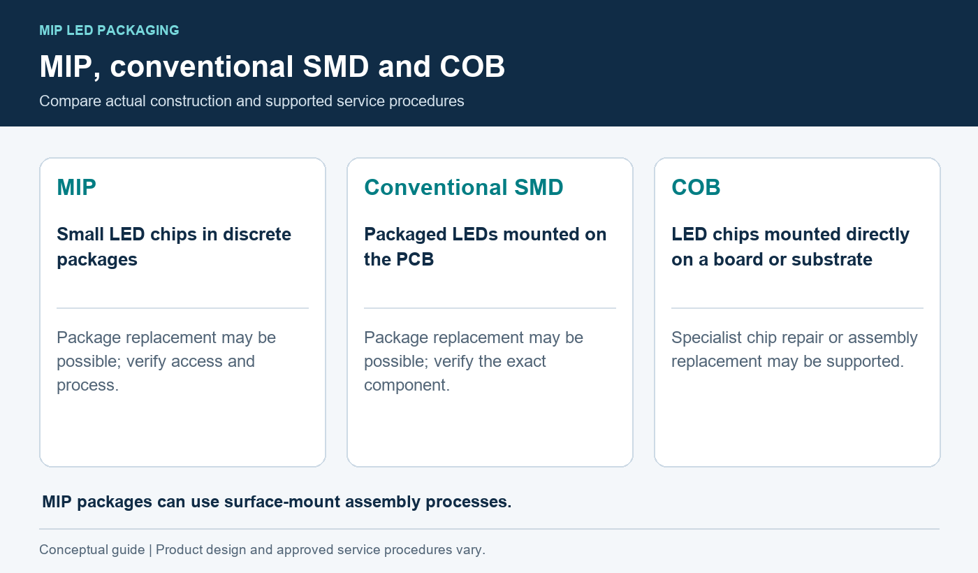
These terms need careful handling. MIP describes a packaging approach, while SMD refers to surface-mounted devices. A MIP package can be assembled using surface-mount processes, so MIP and SMD are not completely separate concepts.
In purchasing comparisons, “SMD” commonly means conventional packaged RGB LEDs. COB generally refers to LED chips mounted directly onto a board or substrate, with the finished structure depending on the product.
01. Package Construction and Module Assembly
The key distinction is where the discrete package exists. MIP LED packaging provides a component between the chips and the module PCB. COB uses a different integration approach.
Neither construction automatically establishes superior contrast, reliability, environmental resistance, or repair cost.
| Comparison point | MIP | Conventional SMD | COB |
|---|---|---|---|
| Basic arrangement | Small LED chips integrated into discrete packages | Packaged LEDs mounted onto a module PCB | LED chips mounted directly onto a board or substrate |
| Component identification | Requires the specified MIP package and revision | Requires the specified LED package and revision | Requires product-specific chip and assembly information |
| Repair approach | Package replacement may be possible | Package replacement may be possible | Specialized chip-level repair or assembly replacement may be used |
| Protective surface | Product-dependent | Product-dependent | Product-dependent |
| Field maintenance | Often based on exchanging a service assembly | Often based on exchanging a service assembly | Often based on exchanging a service assembly |
| Buying priority | Verify the actual rework process and support | Verify compatibility and service capability | Verify supported repair levels and turnaround |
02. Component Replacement vs. Module Replacement
Component repair restores a damaged module by replacing or repairing an individual part. Module replacement exchanges the whole board assembly and restores operation more quickly when a suitable spare is available.
Both approaches can exist within the same maintenance plan. A technician may swap a MIP LED module on-site and send the removed unit to a specialist workshop.
03. Comparing Products at the Same Pixel Pitch
Start with the same screen dimensions, resolution, brightness targets, operating conditions, and service requirements. Then compare samples and supporting documentation.
If the proposals use different cabinets, controllers, warranties, or spare quantities, the price difference cannot be attributed solely to MIP LED packaging.
5. Benefits and Limitations of MIP LED Packaging
The value of MIP LED packaging depends on how its manufacturing characteristics translate into a dependable finished product.
01. Manufacturing Flexibility and Component-Level Testing
Discrete packages provide a stage at which components can be evaluated before they enter the module assembly process. Subject to the package specification and layout rules, they can also support different module designs.
For distributors, component traceability can help connect a replacement request to the correct part. That benefit is strongest when the display supplier maintains clear package, PCB, and production records.
02. Fine-Pitch Assembly and Rework Challenges
Smaller components and tighter spacing can demand more precise placement, inspection, and repair equipment. A package may be individually replaceable in principle while remaining unsuitable for routine repair by an installation crew.
The supplier’s repair demonstration should therefore matter more than a general claim of easy maintenance. Ask who performs the work, where it happens, and which faults qualify.
03. Why Performance Depends on the Complete Display
MIP LED packaging cannot compensate for inadequate power design, poor cabinet alignment, incorrect configuration, or weak after-sales support.
It also does not establish a universal lifespan or failure rate. Such claims need defined test conditions and an explanation of what is being measured.
A sound specification links each claimed advantage to an observable result: acceptable uniformity, a demonstrated service process, or documented replacement compatibility.
6. Can MIP LED Modules Be Repaired? Methods and Limits
MIP LED modules can support component-level repair, but repairability depends on the specific package, board condition, protective surface, equipment, and supplier-approved process.
A useful repair policy identifies the smallest replaceable unit and the conditions under which replacement remains technically and economically reasonable.
01. Diagnosing LED Package, Driver, and PCB Faults
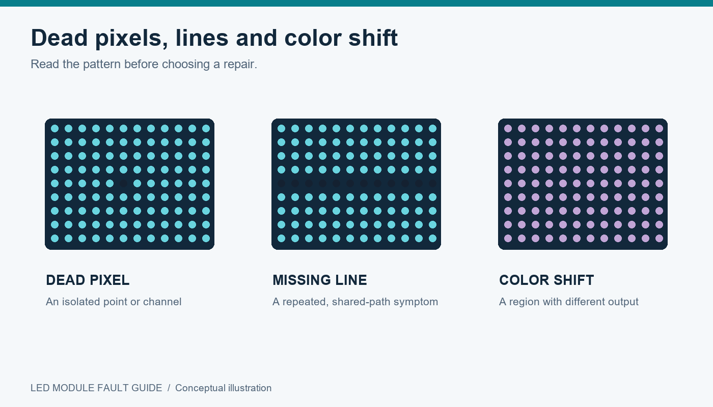
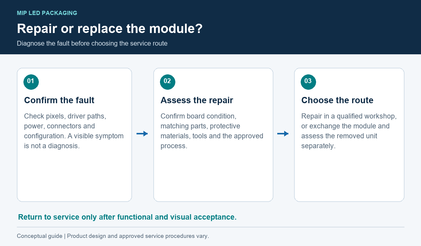
Do not assume that every visible defect originates in an LED package. A line fault, missing region, or unstable image may involve driving electronics, power, connectors, signal distribution, or configuration.
The pattern provides a starting point, not a diagnosis.
| Visible symptom | Possible areas to investigate | Initial service direction |
|---|---|---|
| One dark or incorrect-color pixel | LED package, connection, or local circuit | Confirm the fault with controlled test patterns |
| Repeated row or column defect | Driver path, solder connections, or PCB routing | Trace the shared electrical path |
| Entire module dark | Power, signal, connectors, or module electronics | Verify supplies and connections before component repair |
| Intermittent image | Connections, thermal behavior, or signal integrity | Reproduce the fault under controlled conditions |
| Replacement region looks different | Component matching, settings, or calibration | Verify hardware compatibility before optical adjustment |
Technicians should follow the manufacturer’s isolation and handling procedure. Diagnostic substitutions must use confirmed-compatible parts.
02. Package Replacement: Tools, Skills, and Process Controls
Repairing a MIP LED module may require magnification, precision alignment, controlled rework equipment, ESD protection, and suitable inspection tools.
The process can include removing local protection, extracting the failed package, checking the pads, fitting the replacement, inspecting connections, and restoring the surface where applicable.
There is no universal rework temperature or heating time for MIP LED packaging. Those parameters depend on the component, solder system, PCB, and protective materials. Use the applicable manufacturer process.
03. When Replacing the Entire Module Makes More Sense
Module exchange may be preferable when damage extends beyond one component, the board is distorted, pads are compromised, or restoration cannot achieve an acceptable appearance.
It can also be the better operational choice when downtime is expensive. The removed MIP LED module can be assessed later without keeping the customer’s screen out of service.
04. Checking Image Uniformity After Repair
A repaired module should pass functional and visual checks. Confirm the repaired location, neighboring pixels, grayscale behavior, surface finish, and performance after the specified operating test.
Record the replacement part and repair date. A module that displays an image is not necessarily ready to return to a visually demanding installation.
7. Where Do MIP LED Displays Make Sense?
MIP LED displays are worth evaluating where fine detail and close viewing matter, provided the proposed product meets the installation and maintenance requirements.
01. Control Rooms and Close-Viewing Video Walls
Control rooms may combine small text, charts, and continuous operation. Buyers should evaluate readability, low-brightness uniformity, system redundancy where required, and access for module exchange.
The relevant service question is how quickly the operator can recover an acceptable image, including any required configuration or calibration work.
02. Corporate, Retail, and Broadcast Installations
Corporate and retail displays may prioritize clean visual presentation and limited disruption during maintenance. Service access can be constrained by architectural finishes or narrow installation spaces.
Broadcast applications add camera-specific requirements. Test the complete MIP LED display with representative cameras, shutter settings, framing, and brightness levels. Packaging alone does not establish freedom from flicker or moiré.
03. Matching Display Requirements to Service Capabilities
A capable workshop may make package-level repair practical. A remote installation with limited technical support may benefit more from a straightforward spare-module exchange policy.
| Application | Main evaluation priority | Service-planning priority |
|---|---|---|
| Control room | Fine text and stable image presentation | Recovery time and accessible spares |
| Corporate presentation space | Image quality at normal room lighting | Simple, repeatable module exchange |
| Premium retail | Surface consistency and close-view appearance | Repairs outside trading hours |
| Broadcast studio | Camera compatibility and grayscale behavior | Matching replacements and retained configuration |
| Remote installation | Reliable operation within site limits | Local spare stock and remote support |
Select the complete solution around those needs, rather than selecting MIP LED packaging first and adapting the project afterward.
8. How to Specify MIP LED Modules for Long-Term Service
An effective RFQ makes performance and repair obligations visible before the purchase order is signed.
01. Confirming Package Details and Module Compatibility
Request the package part number, module revision, mechanical drawing, electrical requirements, and control-system configuration. Ask how changes to any of these items will be communicated.
For MIP LED modules, matching dimensions and pixel pitch alone does not prove compatibility. Connector assignments, driving arrangements, mounting details, and optical characteristics also matter.
02. Evaluating Repair Support, Spare Parts, and Warranty Terms
Clarify whether the supplier supports field exchange, local workshop repair, factory repair, or a combination. Request written terms for approved repair methods and warranty treatment.
EagerLED presents a range of LED display categories on its official website. For a MIP inquiry, ask the team to confirm current model availability, the proposed construction, and the applicable service arrangements. Do not assume that every listed display series has a MIP option. EagerLED’s LED display portfolio
| RFQ item | Evidence or commitment to request |
|---|---|
| Package identity | Manufacturer, part number, and approved alternatives |
| Module compatibility | Drawing, revision, electrical details, and mounting arrangement |
| Image acceptance | Defined test patterns, settings, and inspection conditions |
| Repair scope | Supported fault types and smallest replaceable assembly |
| Local repair support | Training, tools, process documentation, and authorization |
| Spare availability | Ordering method and handling of future revisions |
| Warranty | Coverage, exclusions, freight responsibility, and turnaround terms |
| Configuration records | Backup files, firmware references, and calibration information |
03. Requesting Samples and Defining Acceptance Criteria
Evaluate a representative sample using the proposed operating configuration. Where repairability is important, request a demonstration that follows a module from fault confirmation through repair and final inspection.
Include removal, reinstallation, alignment, and data restoration. This reveals practical service requirements that are easy to miss when examining a loose MIP LED module on a workbench.
Record the approved sample configuration so production deliveries can be checked against it.
9. MIP LED Display Costs: Repairs, Spares, and Downtime
The purchase price is only part of the cost of owning a MIP LED display. A repair strategy can reduce component expenditure while increasing labor, logistics, or restoration time.
01. Comparing Equivalent Display Configurations
Compare quotations with the same display size, pitch, image targets, controls, installation scope, and support requirements.
Separate optional items such as spare modules, training, calibration services, and transport cases. This makes it easier to understand what the quoted price actually covers.
Avoid universal claims that MIP LED packaging is cheaper or more expensive than another construction. The answer depends on the products and service arrangements being compared.
02. Budgeting for Field Service and Factory Repairs
A practical ownership budget should include:
- Replacement assemblies and component stock.
- Technician diagnosis and repair labor.
- Access equipment and travel.
- Return shipping and protective packaging.
- Testing, calibration, and reinstallation.
- Operational disruption while the display is unavailable.
For example, a low-cost package replacement may be a poor immediate choice if the module must travel to a distant workshop. A spare-module exchange could restore operation sooner, while workshop repair replenishes inventory afterward.
03. Planning Replacement Stock and Product Availability
There is no universal spare percentage for MIP LED modules. Stock should reflect screen size, fault history where available, repair turnaround, shipping time, and the required response level.
Agree on how discontinued packages or revised modules will be handled. An electrically compatible substitute may still need optical evaluation before joining an existing screen.
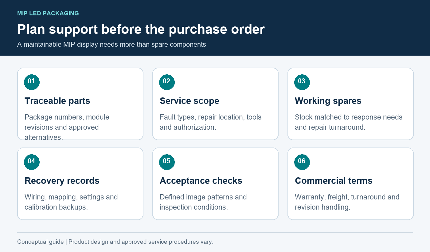
For distributors, the strongest service plan combines traceable parts, a defined return process, and enough working inventory to meet customer commitments.
10. FAQ
01. Can MIP Modules Replace Existing SMD Modules?
Only after the display manufacturer confirms compatibility. Matching pitch and outside dimensions is insufficient. Check the PCB interface, scan arrangement, power requirements, receiving-card settings, mounting points, and visual characteristics. Test the proposed replacement within the actual system before ordering a full conversion.
02. Can MIP Modules From Different Production Batches Be Mixed?
They may be usable together, but matching should be verified. Differences in components, surface finish, operating history, or calibration can reveal a replacement area. Ask the supplier to evaluate the combination under the intended brightness and viewing conditions, including dark content and oblique viewing.
03. Does a Protective Coating Affect MIP Repairability?
Yes, it can change component access and the restoration procedure. Ask whether the coating can be removed locally, which materials are approved for reinstatement, and how the repaired surface is inspected. Do not assume a protective treatment is either fully repairable or permanently unrepairable without product-specific information.
04. Can MIP LED Modules Be Repaired On-Site?
Module exchange may be possible on-site, while package-level rework may require a controlled workshop. The answer depends on the supplier’s procedure, equipment, access, and environmental conditions. Ask the quotation to distinguish clearly between on-site replacement and on-site component repair.
05. Do MIP Displays Require Special Controllers?
MIP LED packaging does not itself define the required controller. Compatibility depends on resolution, driver electronics, receiving cards, scan configuration, and desired functions. Have the supplier identify the complete control chain and provide the approved settings for the selected module revision.
06. Is MIP Packaging Suitable for Outdoor LED Displays?
Some products may be designed for outdoor use, but the MIP designation alone is insufficient. Verify the complete display’s environmental specification, brightness capability, thermal limits, enclosure protection, and connector design. Indoor MIP LED modules should not be treated as outdoor products merely because their chips are packaged.
07. What Configuration Files Should Be Kept for Repairs?
Retain the approved receiving-card configuration, screen mapping, firmware references, and calibration backups where applicable. Connect these records to module and cabinet identifiers. Also retain wiring drawings and the supplier’s restoration instructions so a replacement technician can recover the intended settings without reconstructing the system.
08. Can Replacement MIP Packages Be Bought From Another Supplier?
Potentially, but a similar appearance or package size does not establish interchangeability. Electrical connections, optical characteristics, materials, and process requirements must match the approved specification. Ask the display manufacturer to approve any alternative before using it in a customer installation or warranty repair.
11. Conclusion
MIP LED packaging provides a discrete component structure that can support testing, sorting, and package-level replacement. Its practical value depends on the module design and the service process built around it.
For LED display buyers, distributors, and AV integrators, repairability should be demonstrated through compatible spare parts, approved procedures, accessible assemblies, and verified image quality after restoration. Compare MIP LED modules with other options using the same project requirements and total ownership scope.
For an EagerLED inquiry, provide the viewing distance, display dimensions, operating conditions, access constraints, and expected service response. Request a configuration-specific proposal that explains both how the display will perform and how your team will maintain it.
 Why Use GOB Modules for Outdoor LED Displays?