
Use the checklist with the receiving-card manual and the cabinet’s actual configuration file. Connector labels, voltage requirements, scan modes, and port maps vary by manufacturer.
Table of Contents
- 1. What an LED Receiving Card Does
- 2. Before Wiring: Cabinet-Level Preparation
- 2.1 Confirm the hardware and configuration
- 2.2 Isolate AC power and inspect the cabinet
- 2.3 Identify polarity and voltage
- 3. LED Receiving Card Wiring Checklist
- 4. How to Wire a Cabinet Step by Step
- 4.1 Connect DC power to the receiving card
- 4.2 Connect the HUB board
- 4.3 Build the module data path
- 4.4 Link cabinets in sequence
- 4.5 Apply power and test patterns
- 5. Common Wiring Faults and Fixes
- 6. Final Cabinet Inspection
- 7. Maintenance Practices That Prevent Wiring Failures
- 7.1 Keep a wiring record
- 7.2 Verify after every service change
- 8. FAQ
1. What an LED Receiving Card Does
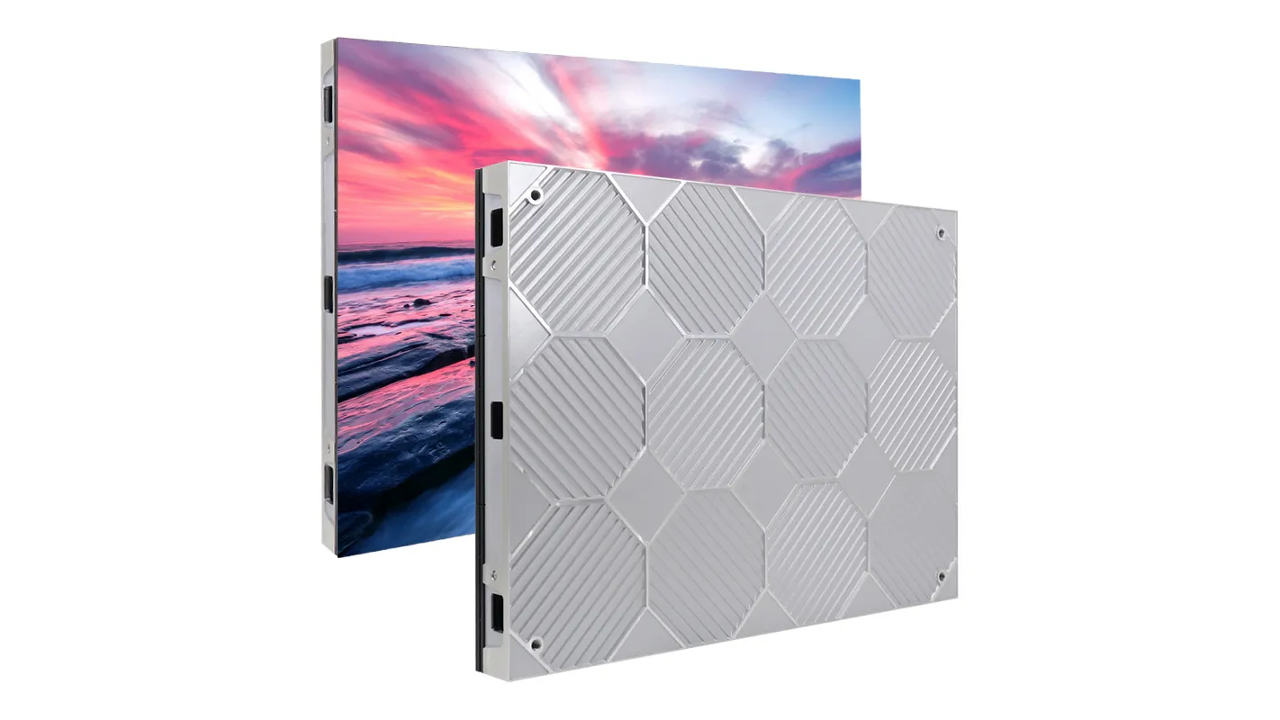
An LED receiving card receives image data from the sending system, interprets the configured pixel layout, and distributes module data through its output ports or a HUB board. It is the cabinet’s data controller. The power supply provides DC power; the receiving card controls how pixels are addressed.
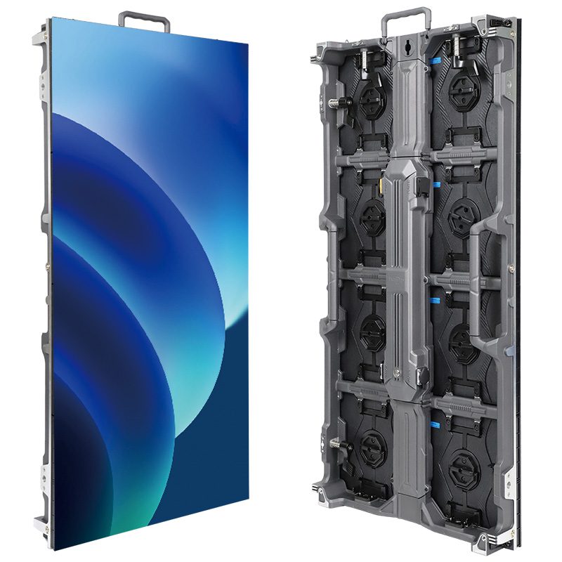
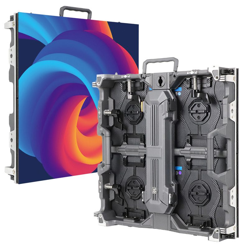
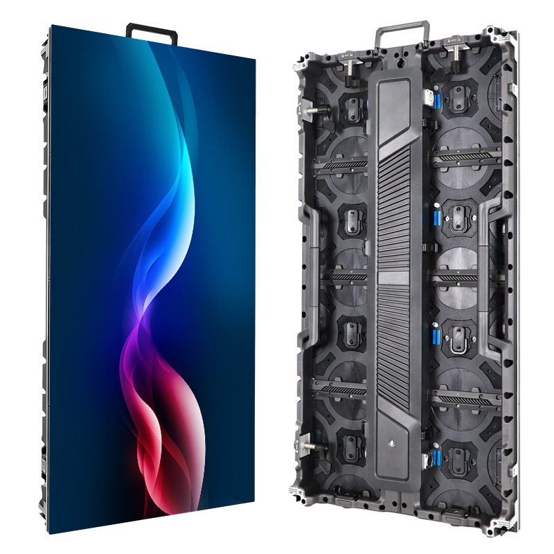
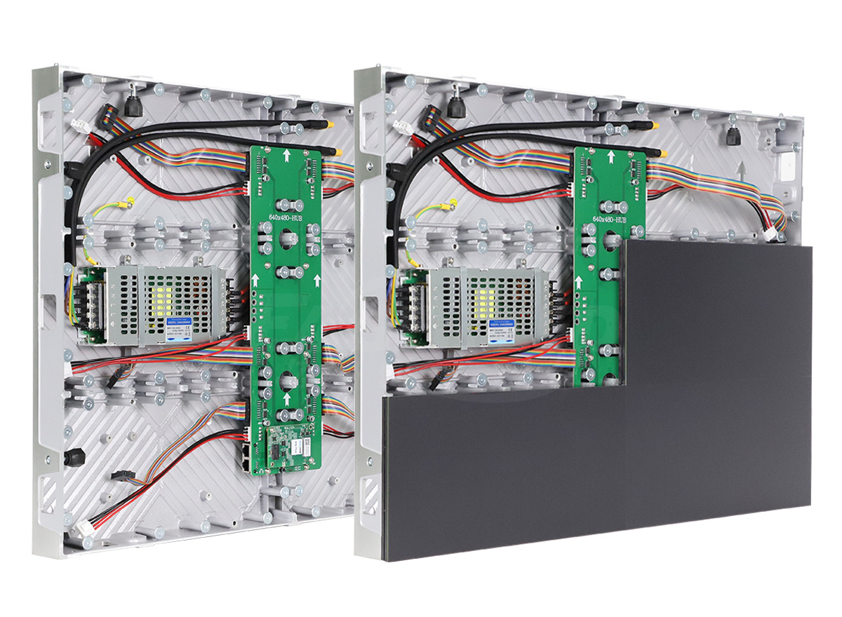
A typical cabinet contains a receiving card, a model-matched DC switching power supply, one or more HUB boards, LED modules, ribbon cables, and RJ45 data cables. The receiving card may also provide status indicators for power, link, data activity, and faults. A lit status LED confirms only one part of the system, so every path still needs a physical inspection.
2. Before Wiring: Cabinet-Level Preparation
2.1 Confirm the hardware and configuration
Record the receiving-card model, module type, scan mode, cabinet resolution, module dimensions, and expected data direction. Keep the correct configuration file available. A physically correct wiring path can still display a scrambled image when the output-port order or scan parameters do not match the file.
2.2 Isolate AC power and inspect the cabinet
Isolate all power sources before changing cabinet wiring. Qualified personnel should verify de-energization; a dark indicator alone is not proof. Separate mains wiring from low-voltage signal cables, check the protective earth connection, and look for pinched ribbon cables, bent header pins, loose terminal screws, and damaged RJ45 plugs. Photograph the original layout when servicing an installed screen.
2.3 Identify polarity and voltage
Read the markings on the receiving card and power supply. Common labels include +5V, VCC, and GND. Never connect a card based only on terminal position. Verify the required voltage in the manufacturer documentation. Only qualified personnel should perform energized measurements using suitable equipment; isolate power again before making connections.
3. LED Receiving Card Wiring Checklist
- Power: Connect the positive DC wire to the positive receiving-card terminal and the negative wire to
GND. - Polarity: Confirm positive and ground at both the power supply and the card.
- Terminals: Tighten screws and ensure no bare copper can touch an adjacent terminal.
- HUB board: Connect the correct receiving-card output to the matching HUB input.
- Ribbon orientation: Align the red stripe, arrow, or pin-1 mark with the connector marking.
- Module input: Connect data to the module’s
INside, following the printed arrow. - Port order: Follow the configured left-to-right, top-to-bottom, or serpentine path.
- Cabinet chain: Follow the documented cabinet link sequence; some cards have interchangeable data ports.
- Final inspection: Check every connector before applying power.
4. How to Wire a Cabinet Step by Step
4.1 Connect DC power to the receiving card
Run the positive and negative wires from the low-voltage output of the power supply to the card’s marked terminals. Keep the run short and mechanically secure. A weak ground can cause flicker, random pixels, intermittent resets, or communication errors even when the card appears powered.
4.2 Connect the HUB board
Fit the manufacturer-matched HUB or adapter board; cards with integrated HUB connectors may need no separate board. Match connector keying, pinout and pin 1 carefully. Do not force a connector: bent pins can create intermittent faults that look like software problems.
4.3 Build the module data path
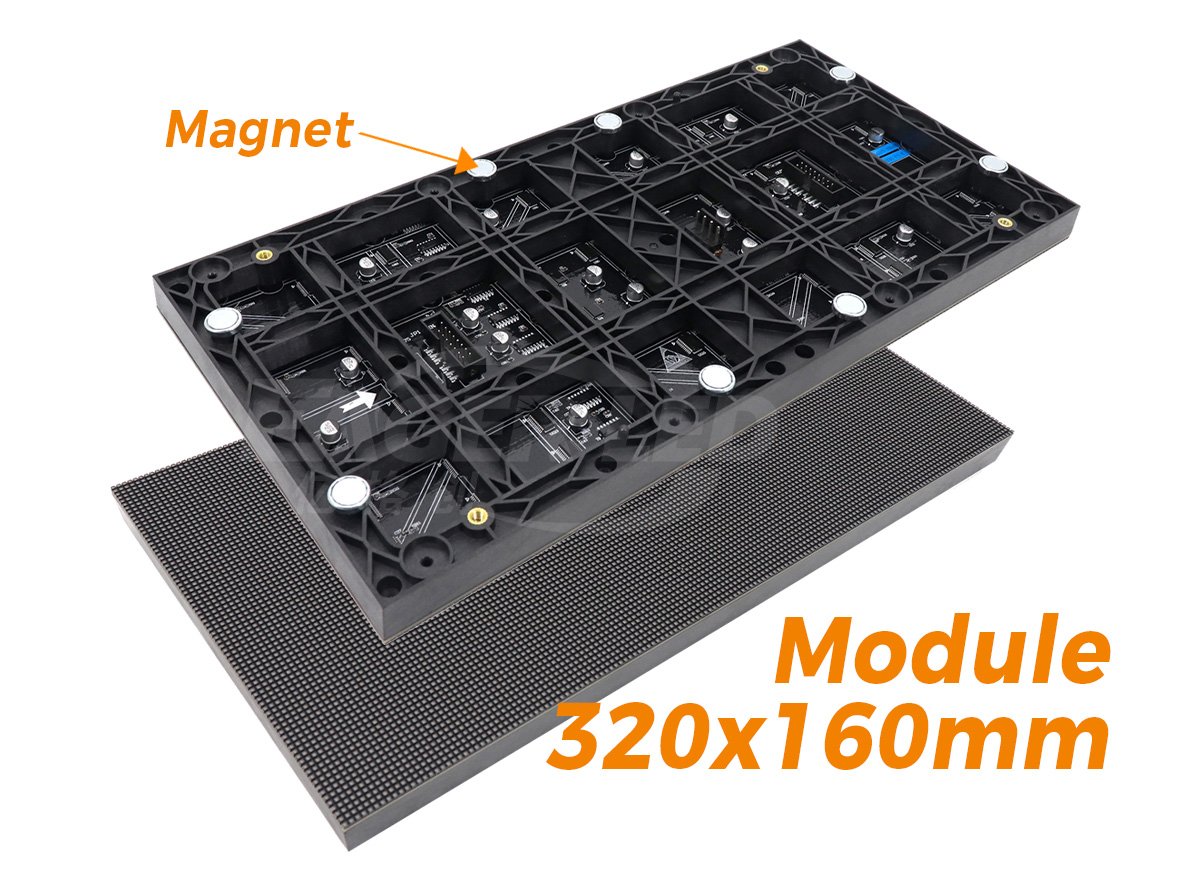
Start with the first module defined by the configuration file. Connect each HUB output to its assigned module input. Daisy-chain module outputs only where the cabinet design specifies it; other designs use independent outputs or direct board connections. A physical position such as upper-left does not determine port 1. Follow the saved mapping and label every branch.
4.4 Link cabinets in sequence
Connect the sending system to the first receiving card, then link the subsequent cabinet. Follow marked IN/OUT ports where provided; check the manual for cards whose two data ports are interchangeable. Keep the physical cabinet order consistent with the screen mapping. A cabinet showing the wrong image area may have a valid link but an incorrect sequence.
4.5 Apply power and test patterns
Power one cabinet first when possible. Observe the card indicators, then display solid black, white, red, green, blue, and gray test patterns. Solid colors expose missing rows, wrong channels, uneven brightness, and intermittent connections more clearly than normal video.
Voltage-drop example: If a nominal 5 V system measures 5.0 V at the supply and 4.6 V at the card under the same load, the difference is 0.4 V. This illustrative measurement points to the supply path, not automatically a failed card. Compare the card reading with its specified operating range. Inspect wire sizing, terminations and shared loads; do not raise supply voltage beyond component ratings to mask a wiring problem.
Watch the official EagerLED EA169F2 assembly tutorial for cabinet assembly and connection context. Hardware layouts differ; follow the manual for your receiving-card model.
5. Common Wiring Faults and Fixes
| Symptom | Likely cause | First check |
|---|---|---|
| Entire cabinet blank | No DC power, reversed polarity, or no data input | Measure voltage and inspect input cable |
| Card powered, modules blank | HUB or ribbon cable disconnected | Reseat the HUB and first module cable |
| One row blank | Broken cable or failed module output | Inspect the preceding module output |
| Image scrambled | Wrong port order or configuration | Compare physical path with the file |
| Flicker or random pixels | Voltage drop, weak ground, or loose signal | Measure under load and tighten terminals |
| Following cabinets blank | Open RJ45 output chain | Check the previous card’s output |
Change one variable at a time. Reseat one connector, test again, and record the result before replacing another cable or changing configuration settings.
6. Final Cabinet Inspection
Before closing the frame, verify power polarity, terminal tightness, ribbon orientation, module data direction, cabinet order, ventilation, and protective earth. Label the receiving-card input and output, first module, last module, and each module row. Save a photo of the completed wiring so future service work starts with a known reference.
For component selection, see our LED receiving card guide. Keep the sending side separate from cabinet diagnostics; our NovaStar MSD300 guide explains that part of the system. For US workplace electrical practices, consult OSHA electrical safety guidance; use the applicable requirements in your installation country.
7. Maintenance Practices That Prevent Wiring Failures
Receiving-card wiring should be checked during commissioning and during scheduled service visits. Vibration, repeated module removal, heat, and dust can loosen connectors over time. Record the cabinet ID, receiving-card model, power-supply output, and data path in the service log. This information shortens diagnosis when a fault appears months later.
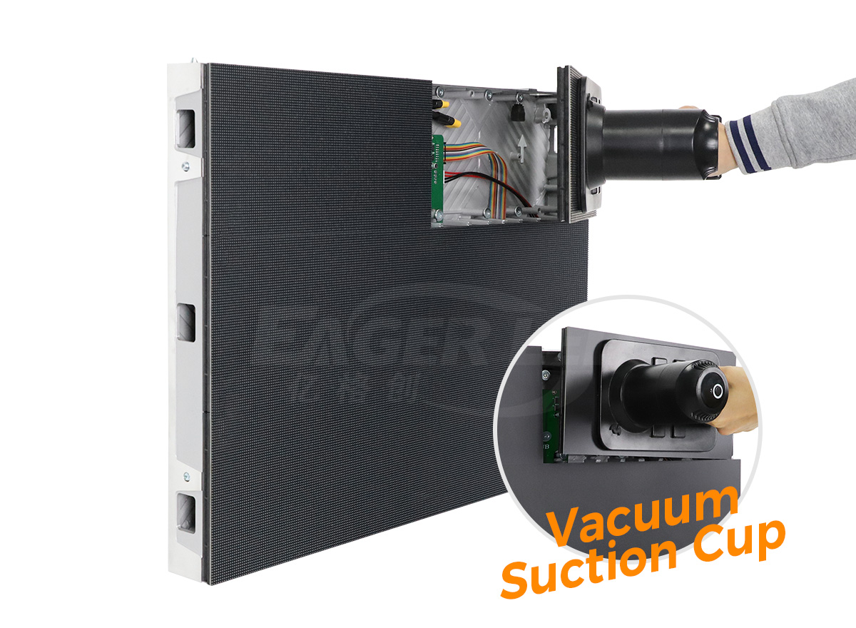
Inspect every output branch, including its first module and downstream connectors. Check for darkened terminals, warm connectors, cracked ribbon housings, and cables pressed against sharp metal. Replace damaged cables with the correct pin count and length rather than forcing a longer cable into a tight bend.
7.1 Keep a wiring record
A useful record includes a cabinet photograph, a simple port map, the installed configuration filename, test-pattern results, and the date of the last inspection. When a receiving card is replaced, update the record immediately. A clear cabinet history prevents technicians from repeating the same tests and helps identify recurring power or signal faults.
7.2 Verify after every service change
After replacing a receiving card, HUB board, module, or ribbon cable, run the same solid-color test sequence used during commissioning. Confirm that the cabinet displays the correct image area and that downstream cabinets remain online. Close the cabinet only after the final test and cable inspection are complete.
8. FAQ
01What voltage does an LED receiving card use?
Many cards use 5 V DC, but always confirm the marking and manual for the exact model before connecting power.
02Can a ribbon cable be connected backward?
Do not assume it is reversible. Align pin 1, the red stripe, or the arrow with the board and module markings, and follow the module’s data direction.
03Why is the receiving card powered but the screen blank?
Check the sending-card link, RJ45 input, HUB connection, first module input, ribbon orientation, and receiving-card configuration.
04Why does only one row fail?
Inspect the row’s first module, the preceding module’s output, and the ribbon cable between them before replacing the receiving card.
05How do I fix the wrong image on a cabinet?
Confirm cabinet order and data direction, then compare the physical module path with output-port order, scan settings, and cabinet mapping.
06Why do downstream cabinets show no image?
Inspect the outgoing RJ45 cable and the previous receiving card’s output. A valid input link does not prove the output chain is connected.
07Should I change software settings before checking cables?
Start with power, polarity, connector seating, and data direction. Change configuration only after the physical path has been verified.
 LED Display Board for Advertising: Pixel Planning