
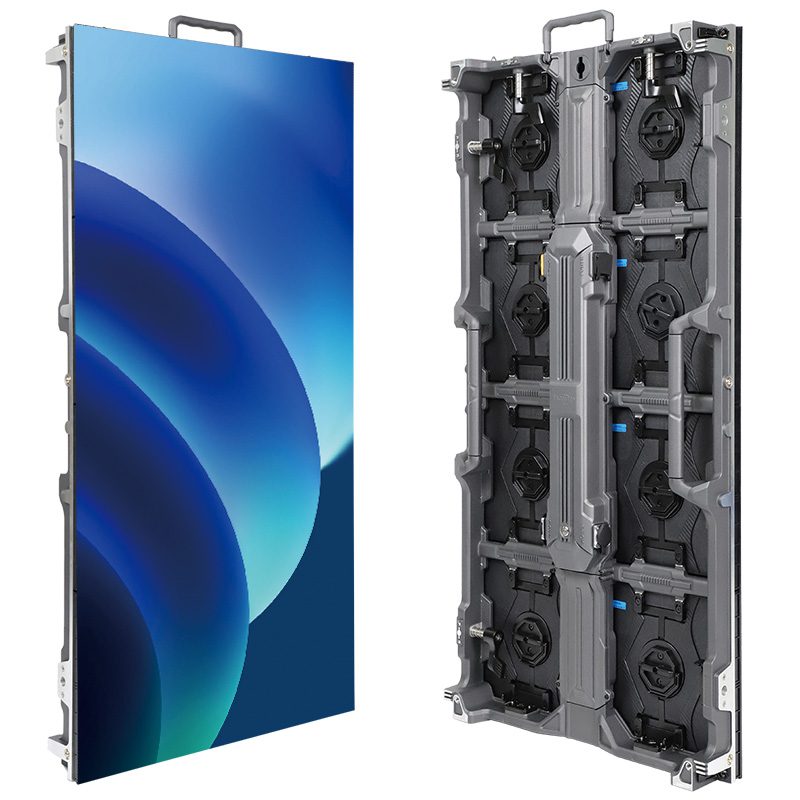
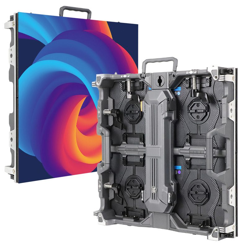
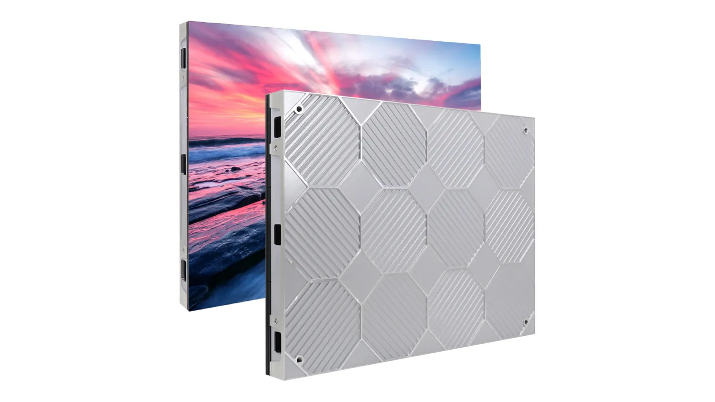
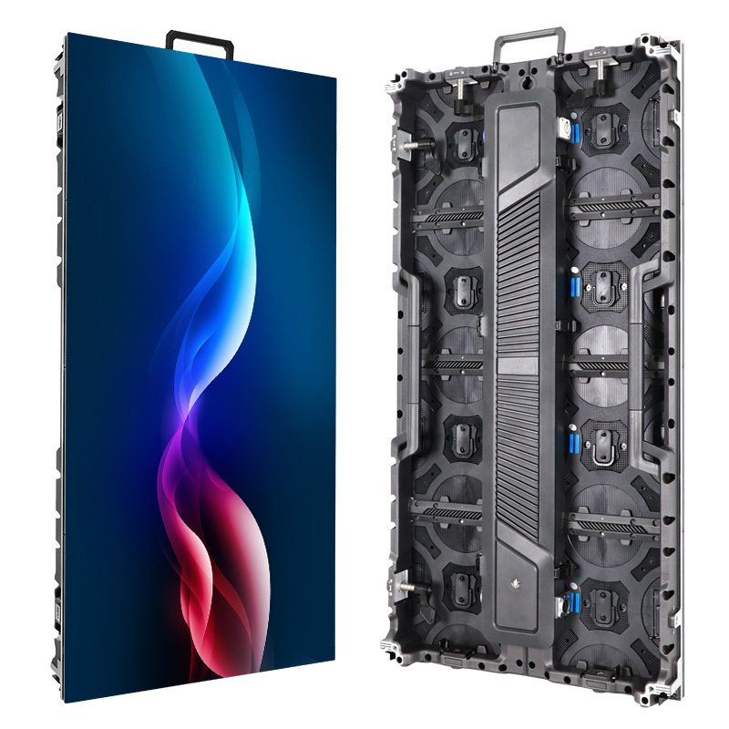
COB LED display manufacturing bonds bare red, green and blue LED dies directly to a circuit board, protects them with an encapsulation layer, and turns the resulting modules into a calibrated video wall. The critical buying question is whether the supplier can demonstrate consistent bonding, surface quality, low-brightness uniformity and reliable service—not simply whether the product carries a COB label.
This guide explains the production process, common defects and practical acceptance checks for buyers, AV integrators and project contractors. A COB LED display can suit close-viewing applications, but its performance depends on the complete module, cabinet, controller and installation. Packaging does not establish a universal brightness, refresh rate, lifespan or waterproof rating.
Table of Contents
1. What Is a COB LED Display?
01. COB LED display construction
COB means chip on board. In a COB LED display, bare light-emitting dies are attached to the printed circuit board (PCB), rather than first being enclosed in separate SMD lamp packages. A protective encapsulant covers the emitting area. The display still contains discrete addressable pixels; a smooth surface does not make its resolution continuous or eliminate cabinet seams.
A COB LED module is one serviceable part of the screen. A cabinet holds modules, electronics and mechanical components; the finished COB LED video wall combines cabinets with receiving cards, power supplies and a control system. Ask which assembly a quotation calls a "panel," because suppliers use that word differently.
02. Wire-bond versus flip-chip COB
Wire-bond construction uses fine wires for electrical interconnection. Flip-chip construction places the die contacts toward the substrate and connects them directly through a suitable bonding process. It removes wire bonds, but still requires reliable electrical and thermal interfaces. "Full flip-chip" should be confirmed for the proposed product, not inferred from a brochure photograph.
COB also describes lighting products such as strips and light engines. Those products have different optical and electrical requirements. Specify a direct-view RGB COB LED display when requesting screen quotations.
2. COB vs SMD vs GOB: Key Structural Differences
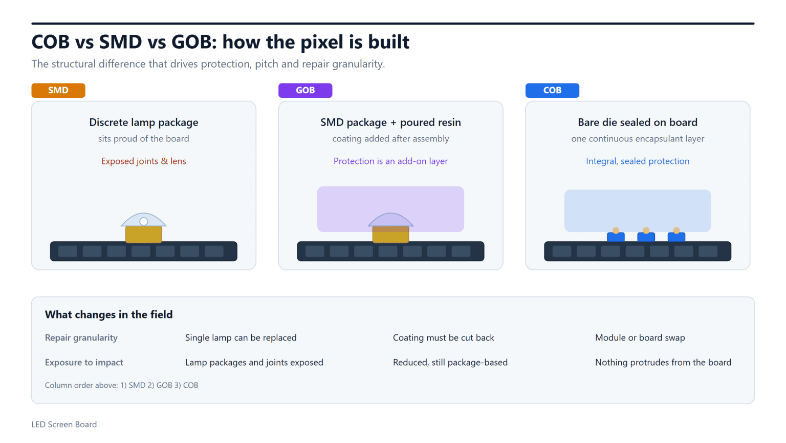
The main distinction is what is mounted on the board and how it is protected. SMD uses packaged LEDs; GOB generally adds a protective coating over an assembled SMD board; COB mounts bare dies directly. None of these descriptions substitutes for a complete product specification.
| Decision point | COB | SMD | GOB |
|---|---|---|---|
| Board-level emitter | Bare dies bonded to PCB | Packaged LED lamps soldered to PCB | Usually SMD lamps beneath an added coating |
| Surface protection | Integral encapsulation over emitting area | Package, mask and product-specific protection | Protective coating over assembled components |
| Fine-pitch selection | Well suited to dense die placement | Depends on package size and assembly capability | Depends on underlying SMD construction |
| Typical service route | Module swap; specialist repair where supported | Module swap or trained lamp-level rework | Module swap or qualified coating removal and rework |
| Evidence to request | Bonding method, surface tests and repair policy | Lamp specification and replacement matching | Coating qualification and repair procedure |
For a broader purchasing comparison, see SMD versus COB LED modules. This article focuses on how manufacturing controls and acceptance evidence affect the delivered screen.
3. COB LED Display Manufacturing Process, Step by Step
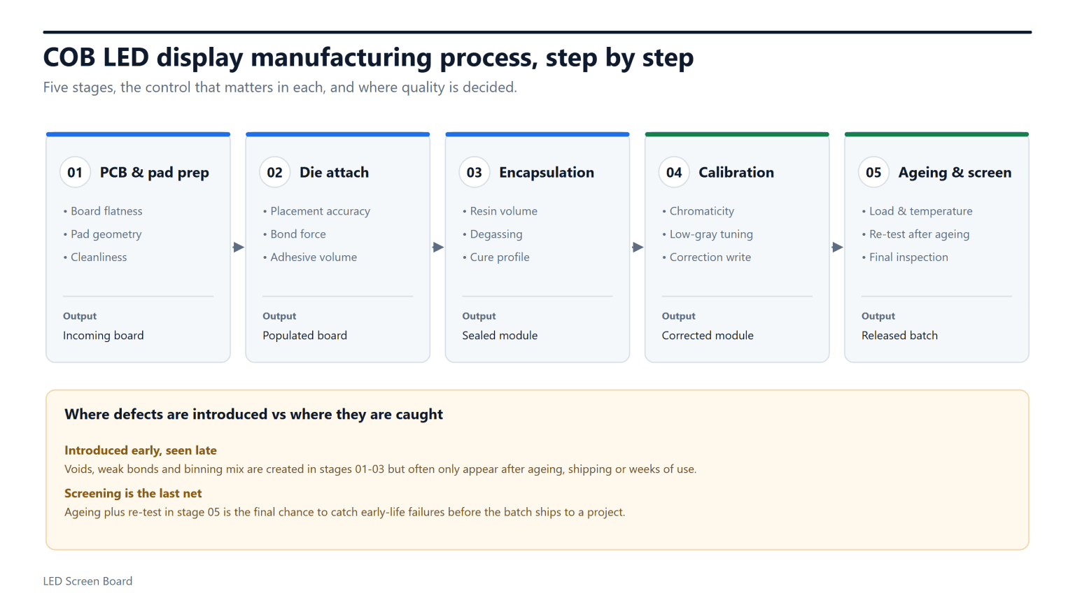
01. Prepare the board and qualify incoming materials
COB LED display manufacturing starts with qualified dies, PCBs, drivers and encapsulation materials. Incoming checks should cover lot identity, board flatness, pad condition and relevant electrical or optical characteristics. Contamination or poor dimensional control can undermine later bonding and cabinet alignment.
Supporting components are assembled according to the validated process route. Die wavelength, brightness and electrical distributions matter: calibration has limited ability to compensate for a poorly controlled material mix, especially at low gray levels.
02. Bond, inspect and encapsulate the dies
Placement equipment positions dies within the specified tolerance. The bonding process controls alignment, temperature, pressure and bonding material as applicable. Electrostatic discharge precautions protect sensitive components throughout handling. Electrical and optical checks before encapsulation help avoid sealing known defects into the COB LED display module.
The encapsulant must cover the emitting area consistently, with controlled thickness, cleanliness and curing. Degassing and process-specific inspection help manage bubbles and voids. There is no single resin recipe or bonding method shared by all COB manufacturers.
03. Calibrate, age and release the finished modules
After assembly, the factory measures brightness and chromaticity, applies calibration and screens the operating modules. The order and repetition of calibration and aging depend on the production route. Buyers should require final verification after the agreed stabilization process, with records traceable to delivered serial numbers.
| Stage | Control objective | Evidence to request | Risk if uncontrolled |
|---|---|---|---|
| Incoming materials | Consistent dies, boards and material lots | Inspection criteria and lot records | Color spread or unstable assembly |
| Die bonding | Correct position and reliable connections | Process limits, optical inspection and sampled bond tests | Dark pixels or intermittent connections |
| Encapsulation | Uniform, clean and properly cured surface | Thickness, cure and void inspection records | Surface defects or optical variation |
| Calibration | Consistent luminance and chromaticity | Measurement conditions and stored correction files | Patchy gray or mismatched modules |
| Aging and final test | Screen early failures and verify released product | Duration, temperature, load profile and retest results | Unscreened failures reaching installation |
| Packing | Protect surfaces, edges and electronics | Serial-number list and packing inspection | Transit damage or lost traceability |
As a documented industry example, Absen describes production monitoring, clean-area controls and ESD precautions in its COB facility. That supports asking suppliers for process evidence; it does not certify another factory's capability.
4. QA Risks in COB LED Display Manufacturing
01. Separate process qualification from shipment inspection
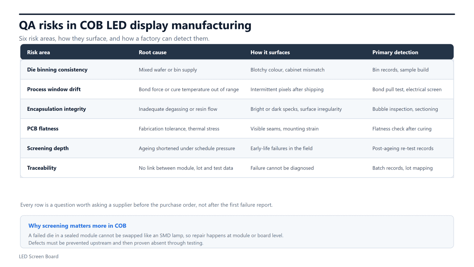
Quality assurance establishes whether the manufacturing process can repeatedly meet requirements. Final inspection checks a particular shipment. A demonstration wall cannot prove either one alone. Ask the COB LED display supplier how equipment is calibrated, material changes are approved and failures trigger corrective action.
Qualification tests may include environmental or mechanical stresses appropriate to the product. These can be performed on representative samples; they are different from routine screening of saleable modules. Ask which tests apply to your model, which are sampled, and which cover every unit.
02. Define measurable acceptance conditions
For COB LED display quality control, replace "excellent uniformity" with agreed conditions: operating brightness, white point, ambient lighting, viewing distance and permitted defects. Specify whether counts refer to pixels, subpixels or modules, and how clusters or bright defects are treated. A percentage without a denominator cannot support acceptance.
Require pre-shipment images and measurements at the agreed settings, together with post-aging results. There is no universal burn-in duration that guarantees reliability. The load, temperature, failure handling and retest procedure matter alongside elapsed hours. The LED module aging workshop overview provides context for discussing this stage.
5. Common COB LED Display Defects and Root Causes
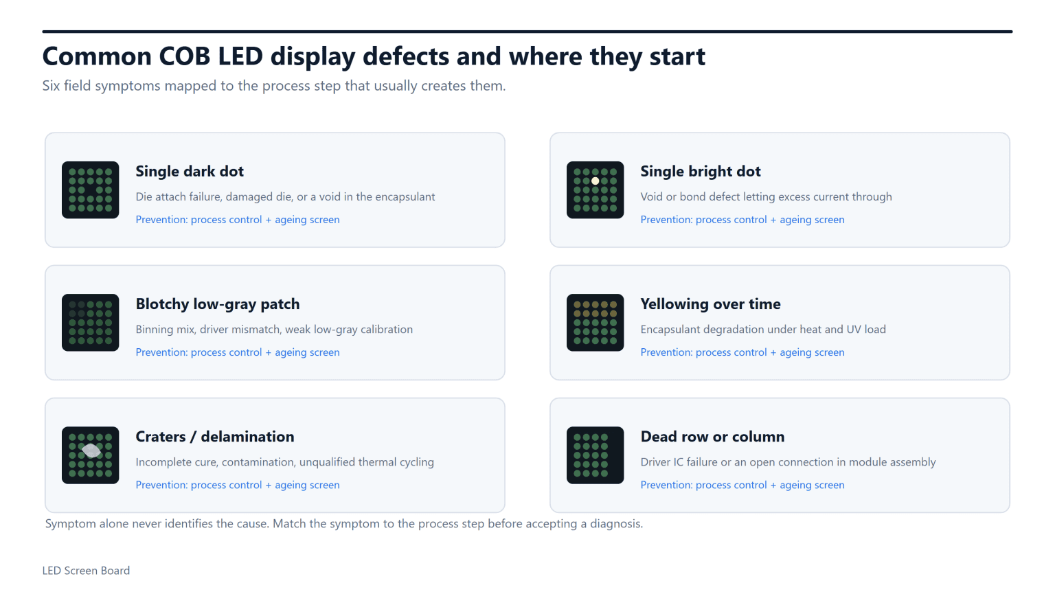
A symptom is a starting point, not a confirmed diagnosis. Before authorizing repair, record the module serial number, operating settings, temperature and whether the fault moves when qualified technicians substitute known-good components. Preserve configuration backups and follow the manufacturer's service procedure.
| Observed symptom | Possible causes | Useful next check |
|---|---|---|
| Dark or bright subpixel | Die, bond, drive-circuit or optical defect | Compare red, green, blue and black patterns |
| Patchy low-gray image | Drive behavior, calibration or material variation | Test gray ramps at intended room brightness |
| Dead row or repeated block | Driver, connection, power or configuration fault | Check the fault pattern against module architecture |
| Visible module boundaries | Mechanical alignment, surface finish or calibration mismatch | Compare screen-off appearance and uniform test fields |
| Crater, bubble or delamination | Contamination, curing, material stress or physical damage | Document surface condition and batch history |
| Color drift during operation | Thermal behavior, settings or component variation | Compare cold-start and stabilized measurements |
Do not cut encapsulation or apply solvents to investigate a COB LED display without an approved procedure. An attempted repair can create additional optical damage and affect warranty coverage. Ask the service team whether module exchange, local specialist repair or factory rework is the supported route.
6. COB vs SMD: Picture Quality and Viewing Angles
01. Compare complete displays at matched settings
A COB LED display can provide a smooth protected surface, but good picture quality also requires consistent calibration and alignment. Compare the candidates at the same luminance and white point. View text, skin tones, neutral gray and slow gradients instead of relying on bright promotional footage.
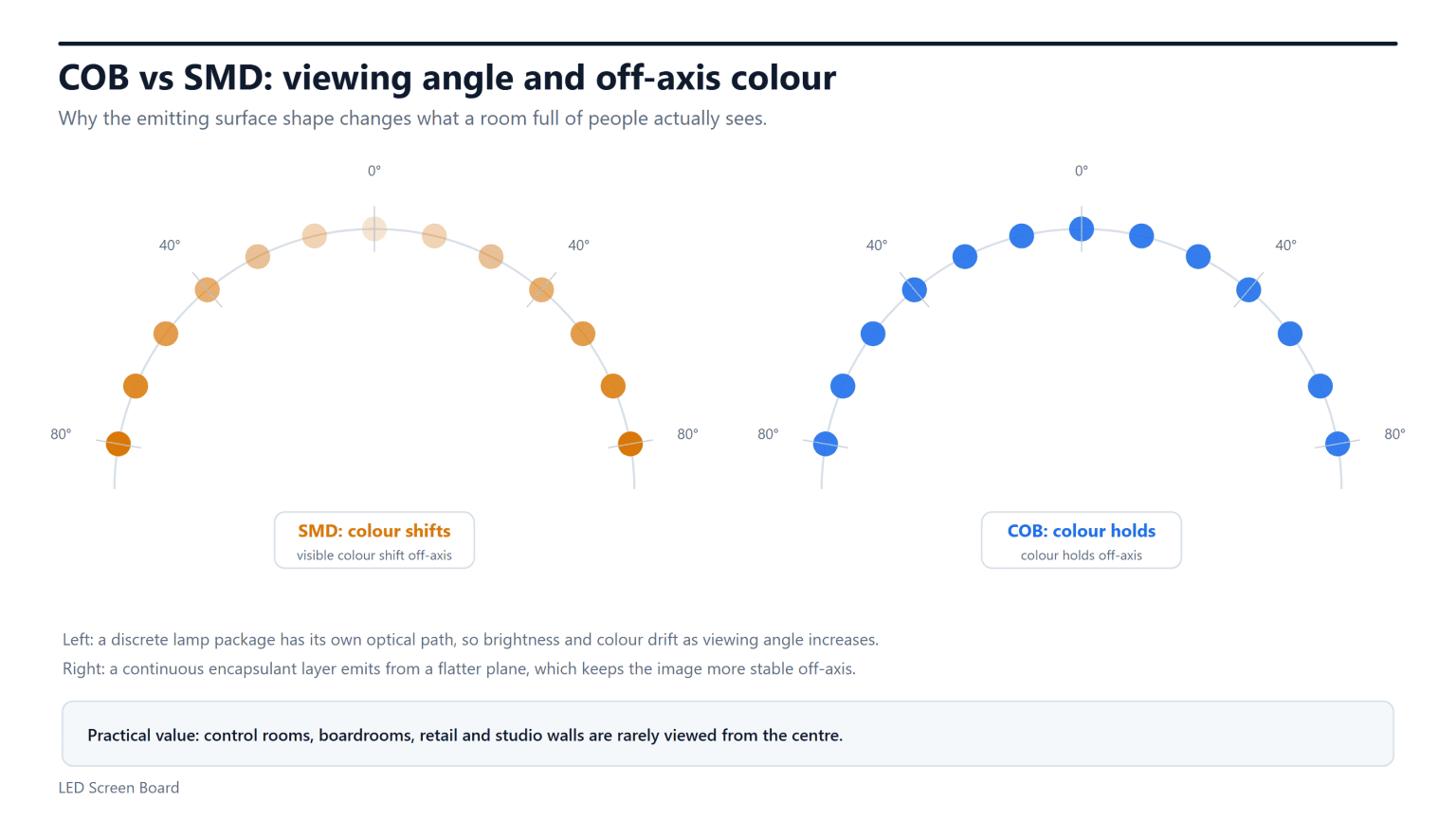
Inspect from the center and actual side seating positions. Check horizontal and vertical color shifts separately. A quoted viewing angle may describe a brightness threshold rather than acceptable color accuracy, so ask how it was measured.
02. Test cameras separately
For studios, a COB LED display still needs testing with the intended camera, lens, distance, frame rate and shutter settings. Moiré depends on interactions between pixel geometry and camera sampling. Banding also depends on driving and synchronization. Neither problem is automatically eliminated by the COB surface.
7. COB vs SMD: Brightness and Color
There is no universal brightness winner between COB and SMD. Die efficiency, drive current, optical layers, pixel density and thermal design all influence the result. Request sustained calibrated brightness for the proposed configuration, together with power consumption and operating limits.
01. Specify useful brightness and low-gray behavior
A COB LED display in a dim control room must look clean at its everyday brightness, not just at maximum output. Check gray gradients, shadow detail and whether dark scenes develop colored patches. Confirm that brightness adjustment preserves usable gray levels and that calibration remains effective over the intended operating range.
02. Evaluate color with a repeatable test
Use the same source signal, white-point target and image mode for both candidates. Record whether measurements were made before or after calibration. Ask for color-gamut definitions and measurement conditions rather than accepting an unexplained percentage. Keep the approved sample settings as the reference for delivery acceptance.
8. COB vs SMD: Resolution and Contrast
01. Calculate resolution from physical dimensions
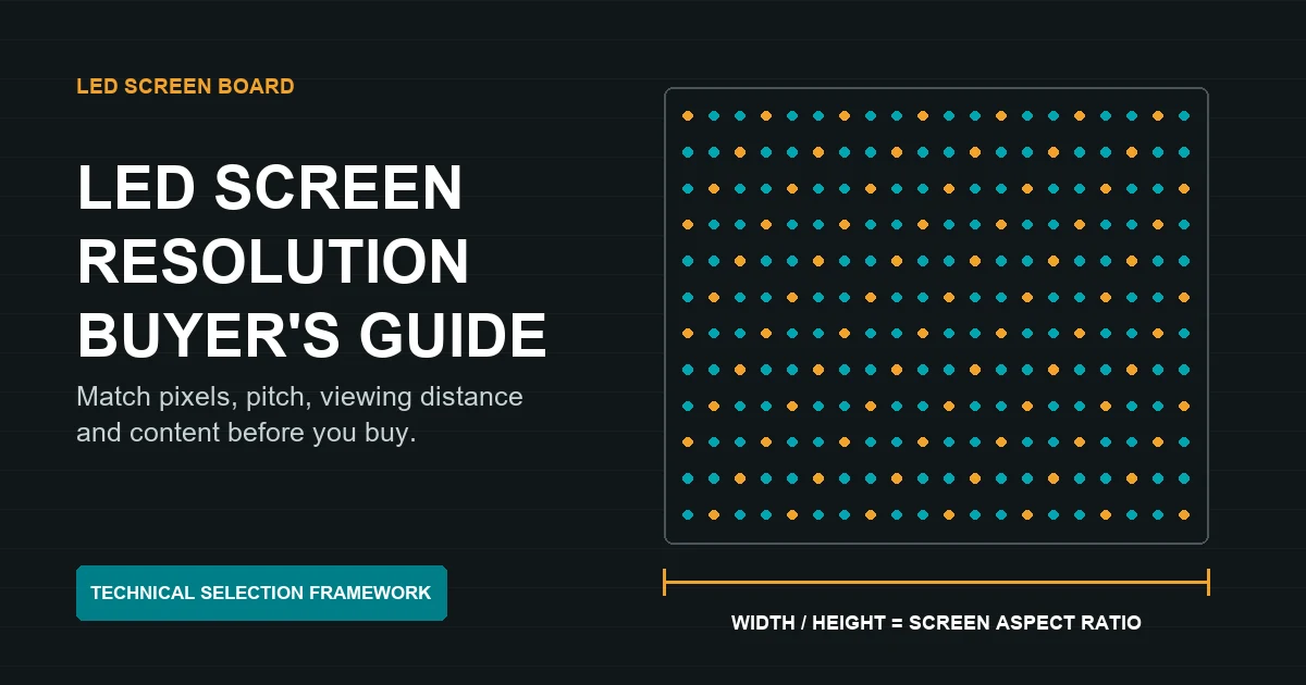
Pixel pitch is the center-to-center pixel spacing. It determines how many pixels fit in a given screen area; COB packaging alone does not make a wall 4K. Calculate horizontal pixels as active width in millimeters divided by pitch in millimeters, then repeat for height.
For example, a 4,800 × 2,700 mm active image at exactly 1.25 mm pitch contains 3,840 × 2,160 pixels. This is an illustrative calculation; actual cabinet dimensions and pixel matrices must match. Use our pixel-pitch guide alongside a viewing test with your smallest text and typical content.
02. Keep contrast and refresh specifications separate
Ambient reflections can reduce perceived contrast even when the COB LED display has excellent dark-room measurements. Inspect the unlit surface under the room's real lights. Matte appearance, black uniformity and seams deserve attention alongside an advertised contrast ratio.
Refresh rate comes from the driving and control system. It is different from video frame rate and does not by itself establish camera performance. Confirm the settings under which the supplier's refresh and gray-scale claims apply.
9. COB vs SMD: Price and Lifespan
01. Compare complete ownership costs
A COB LED display quotation should identify pitch, active dimensions, native resolution, controller, mounting, spares and service scope. Compare equivalent configurations. A lower price per square meter may exclude the items that determine whether the installed system is usable and maintainable.
| Cost category | What to include | Question to resolve |
|---|---|---|
| Acquisition | Modules, cabinets, processing, structure and commissioning | What does the quoted system exclude? |
| Operation | Measured power, operating hours and cooling demand | Were power figures measured at your brightness? |
| Maintenance | Parts, labor, access equipment, freight and calibration | Who pays each cost during warranty? |
| Downtime | Local spares and response arrangements | How quickly can a failed module be exchanged? |
| Future support | Compatible replacements and retained configuration files | How will discontinued modules be handled? |
02. Ask what lifespan and repair promises mean
A lifespan claim may describe light-output depreciation under specified conditions rather than failure-free service for the entire screen. Power supplies, drivers, connectors and environmental exposure also affect useful life. Request the test basis and warranty separately; one is not a substitute for the other.
COB LED display repair is not universally impossible at die level. Specialist capability varies. Unilumin describes customized COB module repair with on-site, local and factory options. Confirm what your supplier actually supports. Module exchange is often the practical uptime strategy, while the removed unit follows an approved repair process.
10. COB vs SMD: Which Is Better for Your Application?
Choose a COB LED display when its verified fine-pitch image, protected surface and service arrangement meet the project requirements. Choose SMD when its demonstrated performance and maintenance economics are the stronger fit. Compare products, not blanket technology rankings.
- Control rooms and boardrooms: prioritize readable small text, low-gray uniformity, operating noise and access for maintenance.
- Retail and public interiors: evaluate reflections, cleaning instructions, incidental contact and replacement matching.
- Broadcast and virtual production: test camera compatibility, synchronization and color behavior across the shooting positions.
- Rental and touring: confirm handling protection, cabinet locks, packing and local repair capability.
- Outdoor installations: require a product explicitly rated for the environment, with suitable enclosure, drainage and thermal provisions.
A sealed COB LED display face does not establish protection for rear electronics, connectors or the complete installation. For exposed locations, review the waterproof LED display selection guide and request the exact product's applicable test evidence.
11. How to Choose a COB LED Display Supplier
01. Request a traceable acceptance package
Ask the COB LED display manufacturer for a documented bill of materials or controlled configuration, module revision, batch identification and test report. A supplier may protect proprietary process details, but should still provide enough evidence to establish repeatability and contractual compliance.
Before volume production, approve a representative sample and retain its settings, measurements and photographs. Require written approval for substitutions affecting optical behavior, compatibility or reliability. The general LED module supplier checklist complements these COB-specific questions.
02. Agree the handover and service procedure
The handover should include cabinet mapping, controller configuration, calibration backups, spare-part serial numbers and maintenance instructions. Request a supervised spare-module replacement demonstration. Confirm that the replacement matches the surrounding screen after the prescribed calibration procedure.
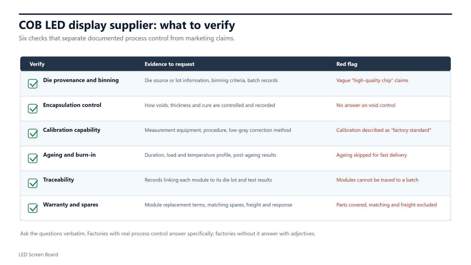
For the final factory acceptance test, inspect uniform colors, black, white, low-gray ramps and representative content after stabilization. Record exceptions before shipping and repeat essential checks after installation. This creates a clear comparison between factory release and site acceptance for the COB LED display.
12. FAQ: COB LED Displays and Manufacturing Quality
01. What does COB mean in an LED display?
COB means chip on board. A COB LED display places bare RGB dies directly on a circuit board and protects the emitting area with encapsulation. It differs from a lighting COB module and from SMD screens assembled with individually packaged LEDs.
02. How is a COB LED display manufactured?
The typical route includes material qualification, PCB preparation, die bonding, electrical and optical inspection, encapsulation, module assembly, calibration, aging and final testing. Factories may repeat or reorder certain checks. Ask for the process and release criteria used for your exact module.
03. Is a COB LED display better than SMD?
It depends on the application and the products compared. A COB LED display can suit close-viewing projects that value dense pixels and surface protection. SMD can offer competitive cost and familiar repair options. Evaluate both at matched brightness, viewing distance and content.
04. Can a COB LED display be repaired?
Yes, but methods vary by design and service provider. A site team may exchange a module while a specialist repairs the removed unit. Confirm supported procedures, matching requirements, turnaround time and warranty terms before purchase.
05. Is every COB LED display waterproof?
No. Encapsulation protects the emitting surface but does not establish the rating of the complete cabinet or installation. Obtain the model's environmental ratings and clarify which surfaces, connectors and installed conditions they cover.
06. How long should COB modules be aged?
There is no universal duration suitable for every design. Require the supplier's validated duration, temperature, load pattern, failure criteria and post-aging retest procedure. An aging-hours claim alone does not demonstrate reliability.
07. What determines COB LED display price?
Pixel pitch, screen area, module design, driver electronics, cabinet construction, processing, calibration, spares and service scope all affect price. Compare a complete installed system at the required performance, rather than unrelated prices per square meter.
08. Which documents should a buyer keep?
Keep the accepted specification, sample measurements, factory and site test reports, serial-number list, calibration and configuration backups, cleaning instructions and written warranty. These records help diagnose faults and maintain a consistent COB LED display over time.
13. Conclusion
A reliable COB LED display begins with controlled manufacturing and ends with measurable acceptance and maintainable installation. Prioritize verified bonding, encapsulation, calibration and aging records; test the screen at its real operating conditions; and agree how replacements will be matched and supported. Those checks make a COB LED display purchase defensible beyond the showroom demonstration.
 LED Receiving Card Wiring: Cabinet-Level Checklist