
LED wall EDID is the display capability information a connected video source reads to find a usable output mode. It can influence the resolution and frame rate a laptop sends. If the processor receives the expected signal but the picture is stretched, cropped, or split across cabinets, check the processor layout and wall mapping before changing EDID.
For AV integrators commissioning an event screen, the practical question is where the picture first stops matching the plan. Record the source output, the input format reported by the processor, and the physical pixel canvas separately. Having those three values makes it easier to reproduce a problem when a presenter changes laptops or a backup source takes over.
1. What LED Wall EDID Tells the Source
EDID stands for Extended Display Identification Data. A display or an intermediate device can describe supported video timings and identify a preferred one. The source uses that information alongside its own graphics capabilities and settings. A preferred timing can influence the default selection, but a source may choose a different supported mode because of its operating system, application, or display configuration.
In a direct connection, the laptop typically reads the information presented by the processor input it is plugged into. Put a switcher, extender, or dock between them and the laptop may instead see information passed through, copied, or generated by that device. Check what the source can see at its connection point, particularly when a format appears on a direct cable and disappears through the event rack.
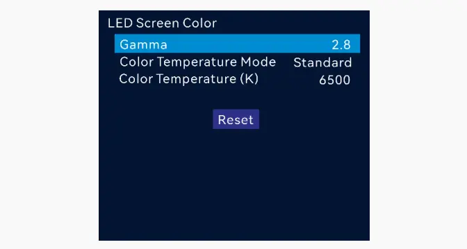
The LED wall EDID can therefore be different at two inputs on the same system. A presenter input might advertise a common resolution that many laptops can deliver, while the media server uses a dedicated connection with a tested custom mode. Manufacturer documentation for the NovaStar H Series, for example, describes custom EDID controls. Confirm the options on the actual input card and firmware before writing them into the show plan.
2. Compare the Input Mode with the Wall Canvas
The input describes the raster arriving at the processor. The physical canvas describes the pixels assembled from the cabinets. A processor can place a layer, scale it, or crop it within that canvas if the hardware supports those operations. It then sends mapped sections to the relevant cabinets. Each of those decisions can affect the picture independently of the LED wall EDID.
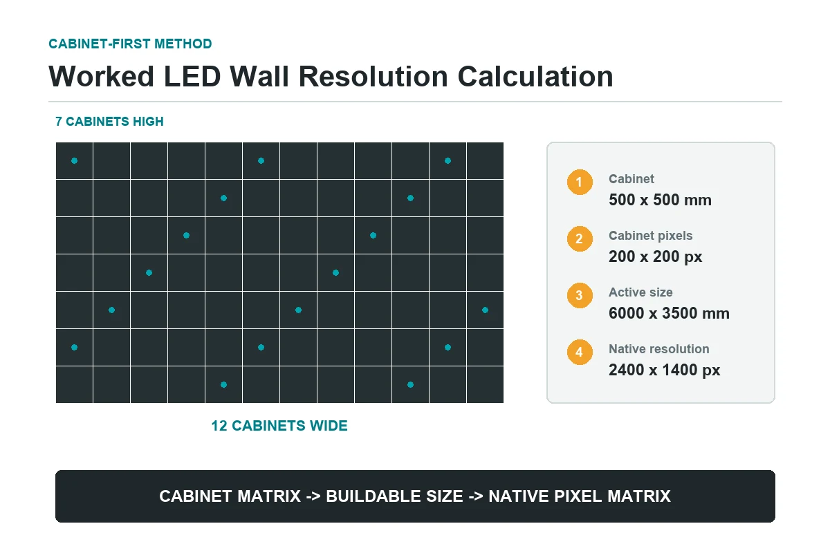
For example, a wall twelve cabinets wide and seven high, with two hundred pixels per cabinet in each direction, has a native canvas of 2400 by 1400 pixels. A laptop feeding 1920 by 1080 can still be an appropriate source. For an aspect-preserving fit across the full width, the image occupies 2400 by 1350 pixels. If centered, that leaves twenty-five unused pixel rows above and below. A fill mode could crop the sides, while stretching to both edges would change proportions.
Request a custom source mode only where it serves a real need, such as a media server delivering fine graphics at the wall’s native pixel dimensions. Check source support and the timing limits of every device between the server and the processor. Resolution and frame rate are only part of the check. The connector, adapter, signal transport, bit depth, and color format may also constrain what the path can carry.
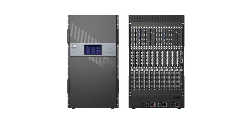
The H20 video wall splicer overview shows a modular processing system and a worked cabinet grid. Treat this as an example of why the screen map and input card belong on the same project drawing. A large cabinet count does not itself tell the laptop which format to send.
For a presentation that mixes slides and video, agree on how unused pixels will look. A centered image can sit on a black background or on a layout designed for the wall. If the layout includes a logo or a ticker, confirm whether it is generated by the source or by a separate processor layer. That determines which team owns placement and which file should carry the margins.
3. Trace a Wrong Resolution to the Right Stage
Start with the exact source and input used when the issue occurs. Read the source’s active output mode and compare it with the resolution and frame rate reported by the processor. Then display material with marks near all four edges and recognizable shapes in the center. A circle makes stretching obvious, while corner labels show which edges are missing or offset.
| What you see | Check first | Record for follow-up |
|---|---|---|
| The expected mode is missing from the laptop list | Advertised modes through the installed connection | Same laptop on the direct input versus the routed path |
| The mode is listed but the processor reports no signal | Active source mode, selected input, and transport compatibility | Format that works with the same cable and adapters |
| The processor receives the intended mode but the image is clipped | Layer size, crop, and position | Missing edge labels and the current layer coordinates |
| Parts of the picture appear in the wrong cabinet positions | Output port map and cabinet order | Row or column labels from the wall test image |
If the source chooses the wrong format, confirm the LED wall EDID through the full path before forcing a new timing. Start with a known working format, then change one setting at a time. If the format at the processor is already correct, use the screen’s test image and the source’s marked image to separate output mapping from layer settings.
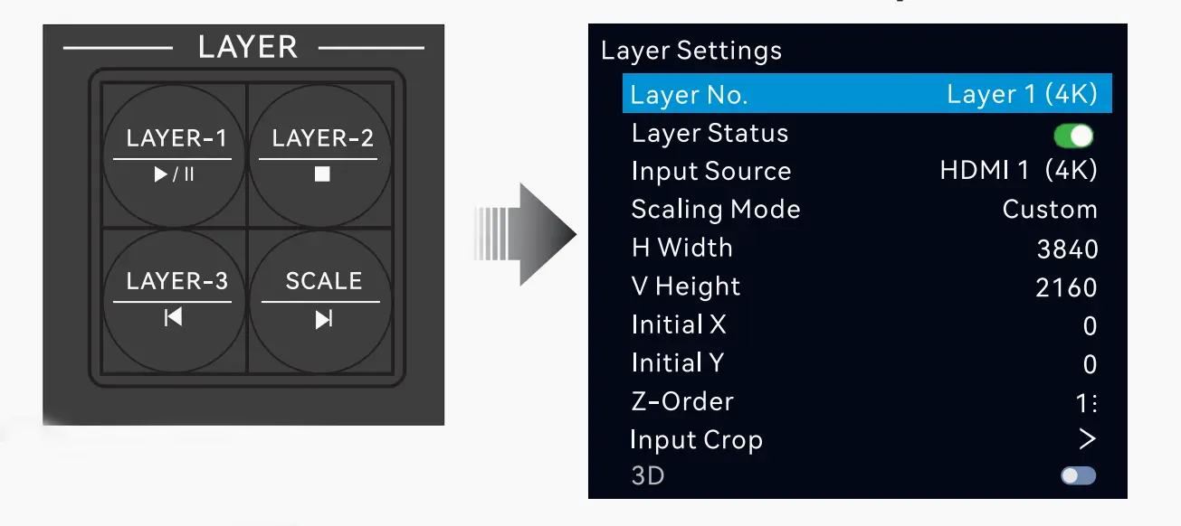
The VX400 Pro controller guide shows a layer menu with separate scaling and crop controls. A width or position change there moves the image on the canvas. It does not change the source’s supported output list. Write down the baseline preset before editing either group of settings.
Consider a rehearsal in which a laptop sends 1920 by 1080 through a short direct cable but drops to a lower resolution when patched through the switcher. Check which mode the laptop selects on each path and which format the processor reports. If the switcher presents a different list of capabilities, check its input profile and the downstream limits before copying the processor profile to it. An advertised mode still needs a compatible path all the way to the selected input.
4. Verify the Agreed Mode Before Handover
Validate the LED wall EDID with equipment the venue will actually use. Include the show laptop, the designated backup source, and any presentation dock or switcher in the installed path. Confirm that each device sends the expected active timing, then check both a border pattern and a representative slide or clip. Content with small type can expose scaling artifacts that a full-screen photograph hides.
Recheck the result after a routine input switch and after a planned reconnect, with the wall available for testing. Document whether a mode must be selected manually or whether the source selects it automatically. A stable session on a single laptop says little about what happens when another device reads the advertised modes for the first time.
Keep a short handover note listing the input labels, expected resolution and frame rate, the wall canvas, the scaling policy, and the fallback mode. Where the processor supports exporting profiles, retain the approved LED wall EDID configuration with the corresponding input and preset identified. Record who should restore it and how the operator can confirm that the image is back to the approved layout.
Give the venue team two screenshots for each approved input: one showing the processor input status and one showing the complete test image on the wall. Pair those with the preset name and the source settings. If a future software or hardware change affects the signal path, repeat the same check before the next show. Recording the actual received timing is especially useful when different devices offer similarly named presets or label nearby frame rates differently.
5. Frequently Asked Questions
Does a 60 Hz input mean the LED pixels refresh at 60 Hz?
No. Input frame rate describes how often the source sends new frames. LED refresh describes how the panel drives its pixels. If filming is part of the project, arrange a test with the production camera and the actual display settings.
Why does duplicating a laptop display change the available modes?
The operating system may choose a mode that both outputs can use in mirror mode. During a rehearsal, test extended-desktop mode and confirm that the application opens on the intended display before relying on it during the event.
Will a custom timing make presentations sharper?
It can help where the source and wall can deliver a true pixel-for-pixel layout. Content scaling can still take place in the application or processor. Verify with fine lines and text at the actual operating distance.
Should we change EDID during a live presentation?
Use an agreed fallback if the show is in progress. A source may interrupt its output while it recognizes the changed capabilities or chooses a different mode. Rehearse the change and the rollback in a maintenance window.
6. Document the Signal Path for Your Project
Before accepting the system, confirm what the source sends, what the processor receives, and where the image lands on the cabinet map. For an LED wall EDID discussion, share the wall dimensions in pixels, the processor model and input card, the source equipment, and the required content formats. Contact EagerLED about your LED wall project to review the signal path and agree on a practical fallback before commissioning.
 LED Cabinet Flatness: How to Check Visible Seams