
LED controller backup planning starts with the failure you need to survive. A second cable, a second controller, and a saved configuration file solve different problems. Specify the protected signal path, reserve enough capacity for the backup route, and demonstrate the required behavior before accepting the system. A spare device in a flight case is a recovery resource; it is not an automatic failover system.
This guide is for AV integrators preparing an LED display for client handover. It provides a practical way to compare proposals and write acceptance tests. The numerical example is hypothetical, and the testing suggestions are planning recommendations, not reported EagerLED test results. Model-specific notes refer to the standard NovaStar VX600, not the VX600 Pro.
1. LED controller backup planning begins with a failure boundary
Write the requirement as an observable event: “If the primary controller loses power, the complete display must continue showing the approved source through the backup controller.” Then state the permitted interruption and who will measure it. This is more useful than requesting a “fully redundant screen,” which leaves the protected components and acceptance criteria undefined.
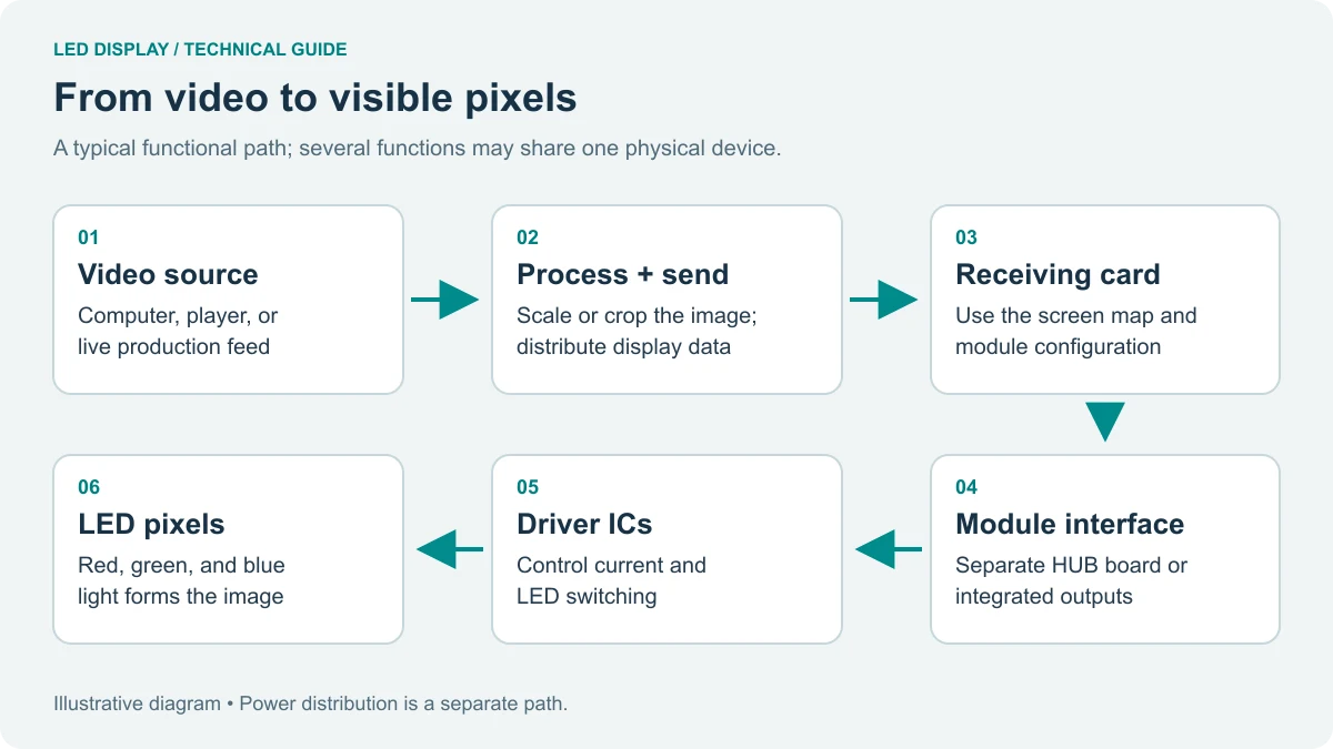
Draw the route from playback computer or switcher to processor, transmission equipment, receiving cards, and modules. Add power supplies and shared distribution devices. Mark every item used by both proposed routes. Two controllers fed by the same single source still depend on that source. Two optical links entering the same converter may still depend on that converter. A common dependency is not automatically unacceptable, but the client should know it exists.
LED controller backup planning should separate continuity during an event from repair after an event. A venue may accept an operator switching to a holding slide during a presentation. A live broadcast may have a different tolerance. Neither requirement can be inferred from a controller’s price or advertised maximum pixel count. Agree on the actual screen behavior before selecting the hardware.
| Failure boundary | What to specify | What this alone does not cover |
|---|---|---|
| Video source or input link | A supported alternate source and switching policy | A failed processor or receiving card |
| Controller output or data cable | A documented alternate path to the affected cabinets | Loss of the only controller’s power |
| Complete controller | A compatible, configured second controller with usable inputs and outputs | A shared failed source or power feed |
| Lost or incorrect settings | Known-good files, version records, and a tested restoration procedure | Automatic continuation while hardware fails |
| Cabinet electronics or power | A separate cabinet-level availability and service plan | Protection from extra upstream cables alone |
Also list deliberate exclusions. For example, the purchase may protect against one output cable failure but exclude simultaneous cable and cabinet-power failures. That statement makes the quotation comparable and prevents a single successful demonstration from being presented as proof of every possible fault.
2. Choose the architecture before ordering duplicate hardware
01. Separate input, port, and device backup
Input backup changes the source presented to a working controller. Port backup provides an alternate transmission route. Device backup introduces another controller. These layers can be combined, but each requires its own compatibility check and test. In LED controller backup planning, “two of everything” is a purchasing description, not evidence that the alternate route will carry the intended picture.
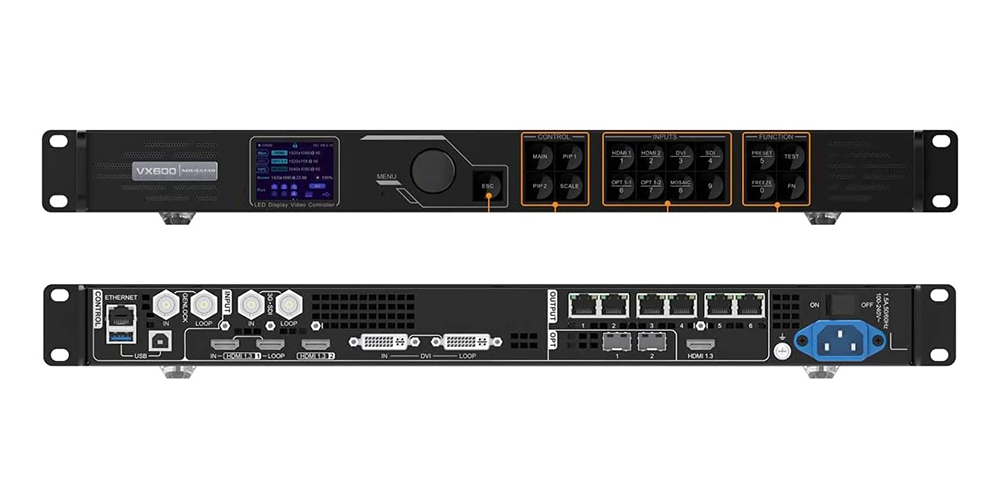
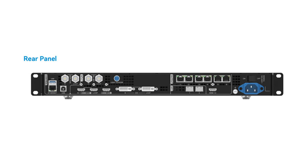
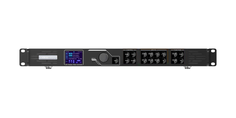
Documented VX600 example: NovaStar’s VX600 All-in-One Controller User Manual V1.4.0, dated July 8, 2024, describes device and Ethernet-port backup in section 5.8.1. For device backup, corresponding ports must serve equal cabinet quantities with reversed data flow, and both controllers must have matching layer settings. Port relationships are configured in NovaLCT. Section 5.8.2 describes input backup between two HDMI sources; restoring the original input does not necessarily switch the active layer back while the alternate source remains valid. These details apply to that documented model and revision. Check the supplied firmware and manual before implementation.
The example shows why a generic wiring sketch is insufficient. Ask for the exact connection drawing and supported pairing for the equipment in the quotation. Use our VX600 overview for product context, but confirm every backup setting against the manufacturer’s documentation for the unit delivered.
02. Identify shared dependencies and separate routes
LED controller backup planning also includes the parts between the boxes. Record patch panels, adapters, fiber converters, source distribution, and cable routes. If both cables cross the same exposed floor joint, one physical incident could affect both. If both controllers rely on the same source distributor, a distributor failure belongs outside the demonstrated protection unless another route is provided.
Do not connect LED data outputs through an ordinary network switch just because the connectors look familiar. Use the manufacturer’s supported transmission topology. Likewise, a management Ethernet connection is not a substitute for the controller’s LED output. Label connectors by function as well as number, particularly when several RJ45 sockets sit next to one another.
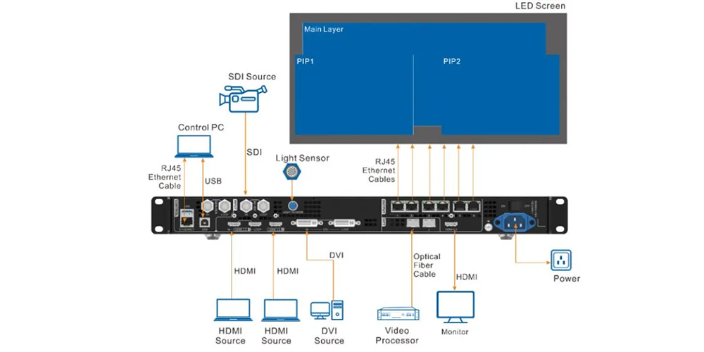
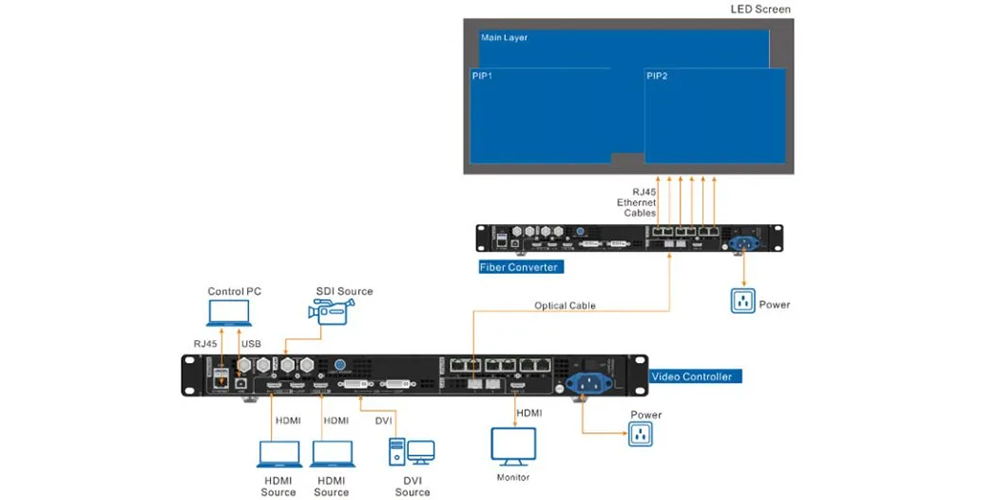
The illustrated fiber arrangement adds transmission components, not an automatic second route. During design review, ask which converter, optical module, cable, and downstream connection would remain available after the chosen fault. Have a qualified electrical professional assess any proposed independent power arrangement; two outlets are not proof of independent supplies.
3. Calculate the load that must survive a failure
Backup ports carry the protected image; they do not create additional unique display pixels. For LED controller backup planning, calculate active cabinet pixels first, then allocate every cabinet to both its normal and intended backup route. A total controller capacity figure alone does not establish whether a particular cable chain or port assignment is valid.
Use actual cabinet resolution rather than rounding dimensions divided by nominal pixel pitch. Check the permitted loading for the chosen frame rate, bit depth, operating mode, and receiving-card arrangement. If the supplier provides a capacity table, retain its revision with the port map. Leave room for documented restrictions instead of assuming that every advertised maximum can be used simultaneously.
Hypothetical planning example: consider a screen with twelve cabinets, each containing 256 × 256 pixels. The active screen has 786,432 pixels. Suppose the proposed topology uses three primary output chains, each with four cabinets, plus three corresponding backup outputs on the same six-port controller. Each primary chain carries 262,144 pixels. The backup outputs repeat those protected regions; they do not increase the screen to 1,572,864 unique pixels.
| Protected region | Cabinet assignment | Primary / backup pair | Pixels carried by either route |
|---|---|---|---|
| Region A | Four cabinets at 256 × 256 pixels | Port 1 / Port 4 | 262,144 |
| Region B | Four cabinets at 256 × 256 pixels | Port 2 / Port 5 | 262,144 |
| Region C | Four cabinets at 256 × 256 pixels | Port 3 / Port 6 | 262,144 |
| Complete active screen | Twelve cabinets | Three protected regions | 786,432 unique pixels |
This table is arithmetic, not a certified wiring design or a claim that every six-port controller supports these pairs. The supplier must validate the receiving-card chain, cable order, port limits, and selected operating conditions. If the proposal instead uses a second controller, its usable capacity must cover its assigned backup regions under those same conditions.
LED controller backup planning must also consider later expansion. If the original design reserves half the available ports for backup, adding cabinets by consuming those reserved ports changes the protection. Require a revised map and new acceptance tests after expansion, even if the enlarged screen still fits within the device’s total advertised capacity.
4. Prepare the configuration, identities, and baseline
Before testing, create a record that another technician can use without guessing. Include controller serial numbers, hardware revisions, firmware, configuration software version, receiving-card model, cabinet resolution, and cable labels. Record the active input timing and processing mode. A successful demonstration has limited value if the delivered system uses different settings.
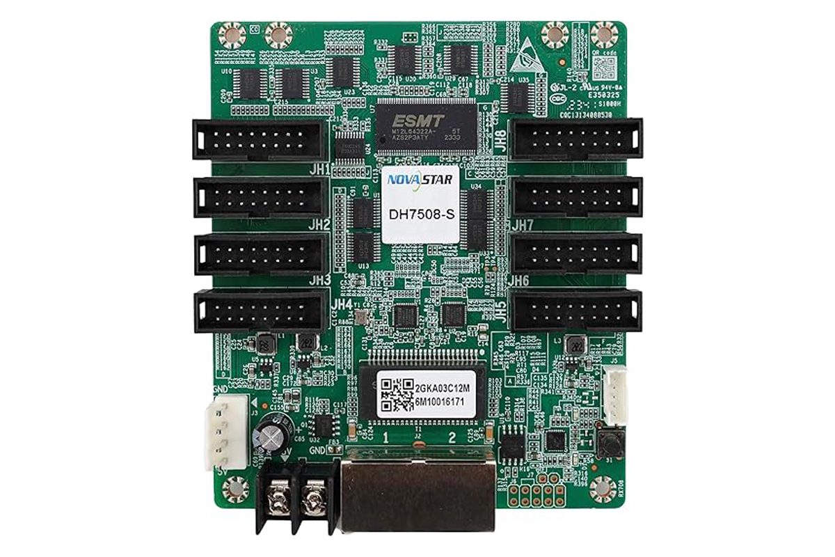
LED controller backup planning requires more than keeping a receiving-card file on a laptop. Preserve the screen connection map, port relationships, relevant presets, source settings, and restoration instructions using the export methods supported by the system. Identify which information each file contains. Do not assume that one file restores the whole installation or that similarly named files are interchangeable.
Our NovaLCT software resource provides a starting point for finding configuration tools. For replacement hardware, the receiving-card replacement file checklist explains the information to collect. Match the configuration to the actual cabinet assembly rather than selecting a file only because the pixel pitch looks familiar.
Use an approved baseline image containing cabinet identifiers, a continuous grid, edge markers, and a moving element. The grid reveals misplaced regions; the moving element helps distinguish live video from a frozen image. Include the client’s real presentation or show content afterward. An internal test pattern checks a different part of the signal chain from a live source, so neither should stand in for the other.
Keep a protected copy of the known-good configuration separate from the working copy. Name the package with a project identifier, configuration revision, and approval date. Record who may change it. If a setting changes during troubleshooting, update the working record and repeat affected checks before promoting it to the new accepted baseline.
For LED controller backup planning, the handover package should also identify recovery tools that must be available locally. A restore procedure that depends on an unavailable laptop, missing adapter, or unknown administrator access has not been demonstrated as an operational recovery method.
5. Test failover, return to service, and saved state
01. Test one agreed fault at a time
Schedule testing during a controlled commissioning window, not during a live show. Confirm the rollback procedure and the person authorized to stop the test. Use the manufacturer’s supported test controls where available. A technician should identify the exact connection before changing it; electrical or cabinet work must follow the equipment’s safe service procedure.
LED controller backup planning becomes verifiable when each test has four parts: starting state, induced fault, expected behavior, and evidence. Observe the complete screen, not just a controller indicator. Record whether content continues, which regions change, whether brightness or color differs, and whether the system reports the expected active route.
| Test | Controlled condition | Evidence to retain |
|---|---|---|
| Input failure | Remove the agreed primary input signal through an approved procedure | Alternate content, switching behavior, and source-status record |
| Output-path failure | Interrupt one identified primary data path | Full-screen recording and affected region’s backup status |
| Device failure | Make the primary controller unavailable using the approved method | Second controller operation and all protected regions |
| Restoration | Restore the failed component or path | Observed return policy, image continuity, and final active route |
| Restart persistence | Perform the agreed controlled restart after configuration is saved | Correct map, settings, and repeated representative failover checks |
02. Define what a pass actually means
“No visible interruption” needs a defined observation method. Agree on the content, viewing position, recording equipment, and timing reference. If the contract requires a maximum interruption time, specify how it will be measured. A handheld recording may document an obvious blackout, but it cannot justify a precise latency claim without a suitable measurement setup.
Do not treat a frozen picture as proof that the intended live service survived. Keep a visible moving marker in the test source. Also check the entire active area: one protected chain may pass while another remains incorrectly mapped. Repeat the relevant test for every protected region rather than extrapolating from the first working pair.
LED controller backup planning should include restoration behavior explicitly. Some arrangements may remain on the alternate route until an operator intervenes or another condition changes. Record what happened and compare it with the approved policy. Unexpected switching back can be as disruptive as failing to switch in the first place.
Finish by restoring normal service, confirming all intended outputs are enabled, and saving the final approved configuration. Remove temporary test settings and record unresolved issues. After a controlled restart, verify the baseline again. A system that works only until its next restart has not met a requirement for persistent protection.
6. Turn the plan into a comparable quotation
Ask suppliers to price the same protection boundary. List primary and backup controllers, transmission equipment, optical modules, cables, source distribution, configuration work, and acceptance support separately. Identify excluded items such as the playback system, local electrical work, or spare cabinet electronics. This makes a lower equipment price easier to interpret.
Attach the proposed port map and test matrix to the purchase discussion. For LED controller backup planning, the useful commercial question is not simply whether redundancy is supported. Ask who configures it, who witnesses the test, what evidence is delivered, and what happens if the demonstrated behavior misses the agreed requirement.
Define changes that require retesting: controller replacement, firmware updates, receiving-card changes, revised cabinet layout, altered input timing, or reassigned outputs. Keep the maintenance responsibility clear after handover. A configuration accepted for one event layout does not automatically validate a different layout assembled from the same inventory.
Separate a warranty claim from an acceptance failure. Hardware can power up correctly while the agreed backup topology remains unconfigured. Conversely, a successful commissioning test does not establish an unlimited service-life guarantee. Record both the supplied equipment and the demonstrated operating conditions so future support starts with reliable information.
Include operator training in LED controller backup planning. Ask the person who will actually run the display to identify the active route, recognize the agreed alarm or status indication, and follow the recovery instructions. Perform this exercise with the final labels and handover documents. If only the commissioning engineer understands the arrangement, revise the instructions before the project changes hands.
A useful evidence package links each test result to a drawing revision and equipment list. In LED controller backup planning, a video named only “backup test” is difficult to audit later. Add the tested fault, affected region, source content, starting state, observed outcome, and witness. Keep failed attempts with the corrective action record rather than retaining only a successful clip without context.
Frequently asked questions
Can a spare controller in storage count as redundancy?
It can support manual recovery, but it does not provide automatic failover while disconnected. Specify the replacement time, configuration restoration process, and operator availability separately from any live backup requirement.
Will input backup detect a frozen playback application?
Do not assume it will. A frozen application can still output a valid video signal. Ask which fault conditions the controller detects, then test the application failure separately from physical signal loss.
Does a second data cable protect a failed receiving card?
Not by itself. An alternate cable may preserve a supported data route, but it cannot repair failed electronics. Receiving-card or module protection requires a separately specified architecture or service plan.
Can primary and backup controllers use different firmware?
Use only a combination the supplier or manufacturer confirms as compatible. Record both versions and test that exact pair. A matching model name alone does not establish that settings and backup behavior will match.
Should the backup source show identical content or a holding slide?
Choose according to the client’s operational requirement. Identical live content and a safe holding slide are different acceptance outcomes. Agree on the fallback content, its owner, and the operator’s return-to-program procedure.
Prepare your project review with EagerLED
For LED controller backup planning, send EagerLED the cabinet resolution and layout, controller and receiving-card models, source format, proposed cable routes, and the faults the display must tolerate. Include the current configuration revision if you are extending an existing installation. Mark undecided items clearly.
Request an equipment and configuration review with the protection boundary and acceptance matrix attached. Ask the proposal to identify supported combinations, excluded failure scenarios, and the tests to be completed before delivery or handover.
 Vertical LED Screen: Portrait Does Not Mean 9:16