
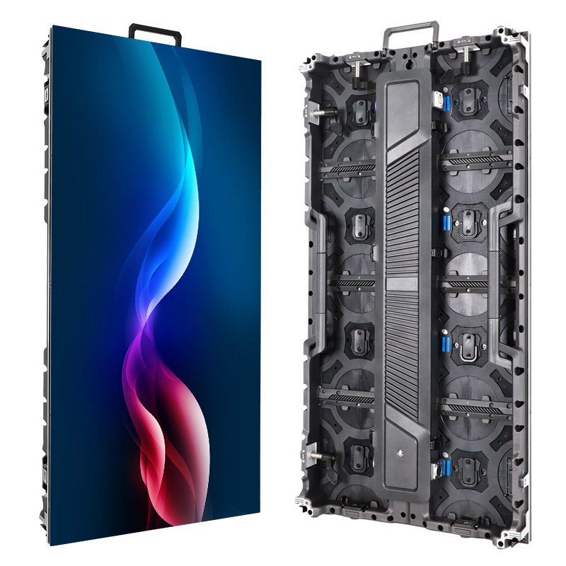
LED display signal flow describes how a picture travels from a video source through processing and sending hardware, receiving cards, module interfaces, and LED drivers. Pixel mapping assigns each part of that picture to a physical location. Power follows a separate distribution path, even when power and data connections sit together inside a cabinet.
An LED screen board is a direct-view display built from illuminated modules. This guide is for project engineers and buyers reviewing a proposed control layout before commissioning. It follows one rectangular wall from source to pixel, with a worked coordinate example and checks you can discuss with the system supplier. For general display types and costs, start with our LED screen board buying guide.
1. Read the Complete LED Display Signal Flow
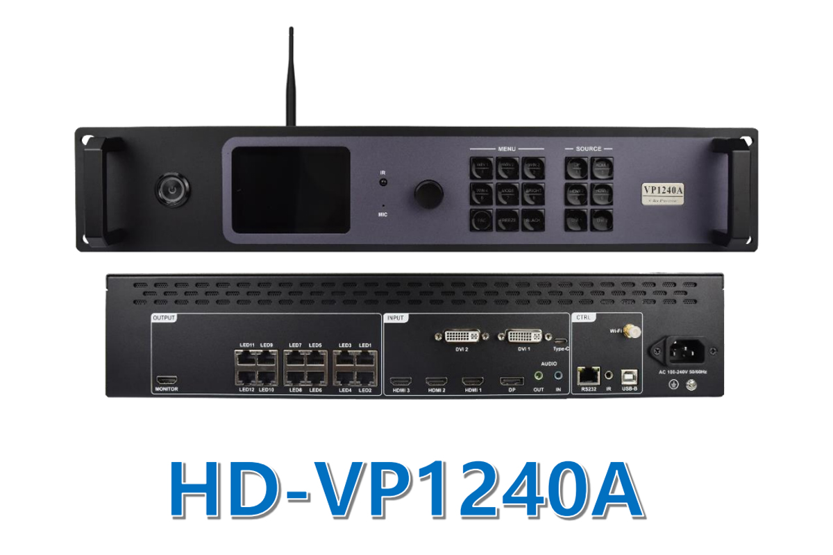
A typical synchronous system follows this chain: source → processor/sender → receiving card → HUB or module interface → driver circuits → LEDs. The arrows describe functions, not a mandatory number of boxes. An integrated controller may process and send, while a receiver may connect directly to modules without a separate HUB board.
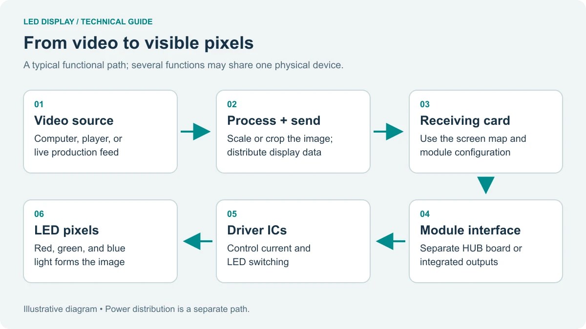
01. Separate the picture from the instructions
The live picture and the configuration are different kinds of information. Video supplies changing image content. Configuration tells the system how much area each receiver controls, where that area belongs, and how its outputs operate the connected modules. A reachable controller does not prove that a valid picture reaches every cabinet.
When documenting LED display signal flow, label the source, controller model, output ports, receiver positions, and module interfaces. Add the direction of each connection. A photograph of tidy cables cannot replace this diagram because it rarely reveals the intended image coordinates or configuration version.
02. Live input versus stored playback
A synchronous installation follows an incoming video source. An asynchronous player runs stored content, usually with a playlist or schedule. Some devices support both workflows. Identify where playback originates before tracing a fault: losing a laptop connection and losing a remote upload connection may have very different effects on the displayed image.
2. Match the Video Source to the Pixel Canvas
LED display signal flow begins with a defined source format and a defined destination canvas. Record the incoming width, height, frame rate, and relevant signal format separately from the physical display resolution. A controller accepting a large input signal does not give a smaller wall additional physical pixels.
01. Native pixels and source resolution
For a regular wall, multiply the pixels in one cabinet by the number of cabinets across and down. Use the actual cabinet pixel dimensions from the approved specification. Physical width divided by nominal pitch is useful for planning, but rounded pitch labels can produce misleading results.
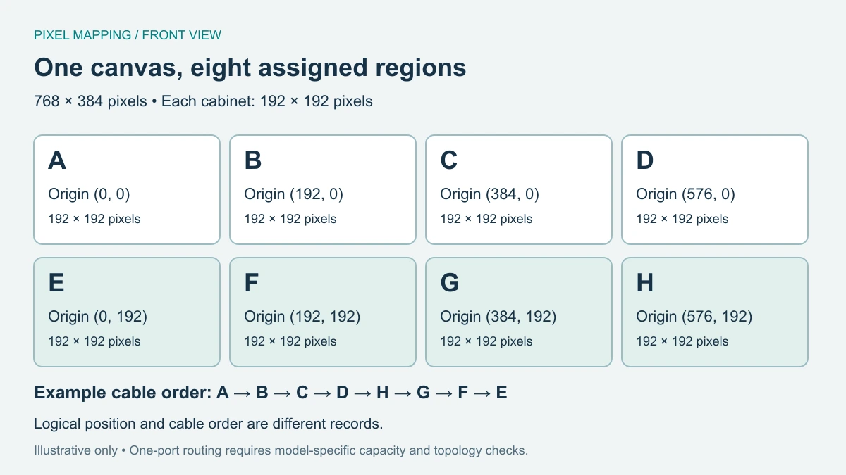
Our worked example uses eight hypothetical cabinets, each 192 × 192 pixels, arranged four across and two high. The wall is therefore 768 × 384 pixels, with a 2:1 aspect ratio. These dimensions are an arithmetic example, not a specification or capacity claim for an EagerLED product.
02. Fit, crop, or stretch deliberately
A 1920 × 1080 source is 16:9. If proportionally fitted within the example canvas, it occupies 682.67 × 384 pixels mathematically; practical scaling uses a supported integer output region. Unused side space remains. Filling the full width proportionally produces a 768 × 432 image, so some vertical content must be cropped. Stretching fills the canvas but changes proportions.
Choose the treatment with the content owner. For presentations, preserve circles, faces, and text proportions. For advertising, prepare artwork for the native canvas where practical. An approved LED display signal flow drawing should identify the scaling or cropping stage so a later operator does not compensate for the wrong setting elsewhere.
3. Identify Video, Control, and Display Interfaces
Do not classify a connection by its plug alone. In LED display signal flow, an input carrying video, a port used to configure a controller, and an output carrying display data perform different jobs. Check the labels and the manual for the exact hardware revision.
01. Similar connectors can serve different functions
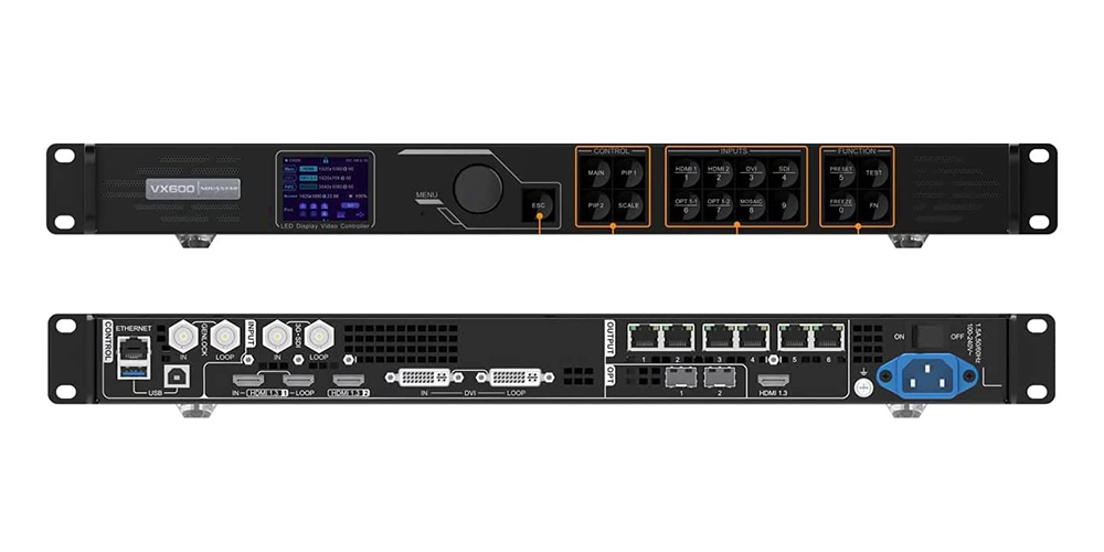
HDMI, DVI, DisplayPort, or SDI may serve as video inputs when the controller supports them. USB or a network connection may be used for management. RJ45-style outputs commonly connect sending hardware to receivers, but their presence does not establish support for an ordinary network switch, router, or power-over-Ethernet device.
Likewise, an optical connector does not establish compatibility between arbitrary transmitters and receivers. Confirm the supported conversion hardware, fiber arrangement, and distance for the selected system. Keep video transport and office-network management clearly labeled on drawings and cable schedules.
| Connection boundary | Evidence to request | Assumption to avoid |
|---|---|---|
| Source to processor | Supported timing, connector standard, and content requirements | A matching plug accepts every source format |
| Computer to control port | Supported software and management connection | Control access proves video is present |
| Sender to receiver chain | Approved cable, topology, distance, and port allocation | Every RJ45 link belongs on the office LAN |
| Optical transport | Matched endpoints and the supported fiber specification | All fiber converters are interchangeable |
| Receiver to module | Output assignment, pinout, scan configuration, and driver support | Same header size means electrical compatibility |
02. Record boundaries before connecting equipment
Give cables identifiers that match the drawing, such as controller output P1 to cabinet A. Record both endpoints and distinguish front-view cabinet coordinates from a technician’s rear view. Our LED control system overview explains the main control arrangements; the delivered equipment documentation must settle model-specific interface questions.
4. Follow Data Inside the LED Module
The final electronic stages of LED display signal flow happen behind the visible LEDs. A module contains the LEDs, a printed circuit board, driver electronics, connectors, and mechanical support. The receiving system must output data and timing suitable for that particular assembly.
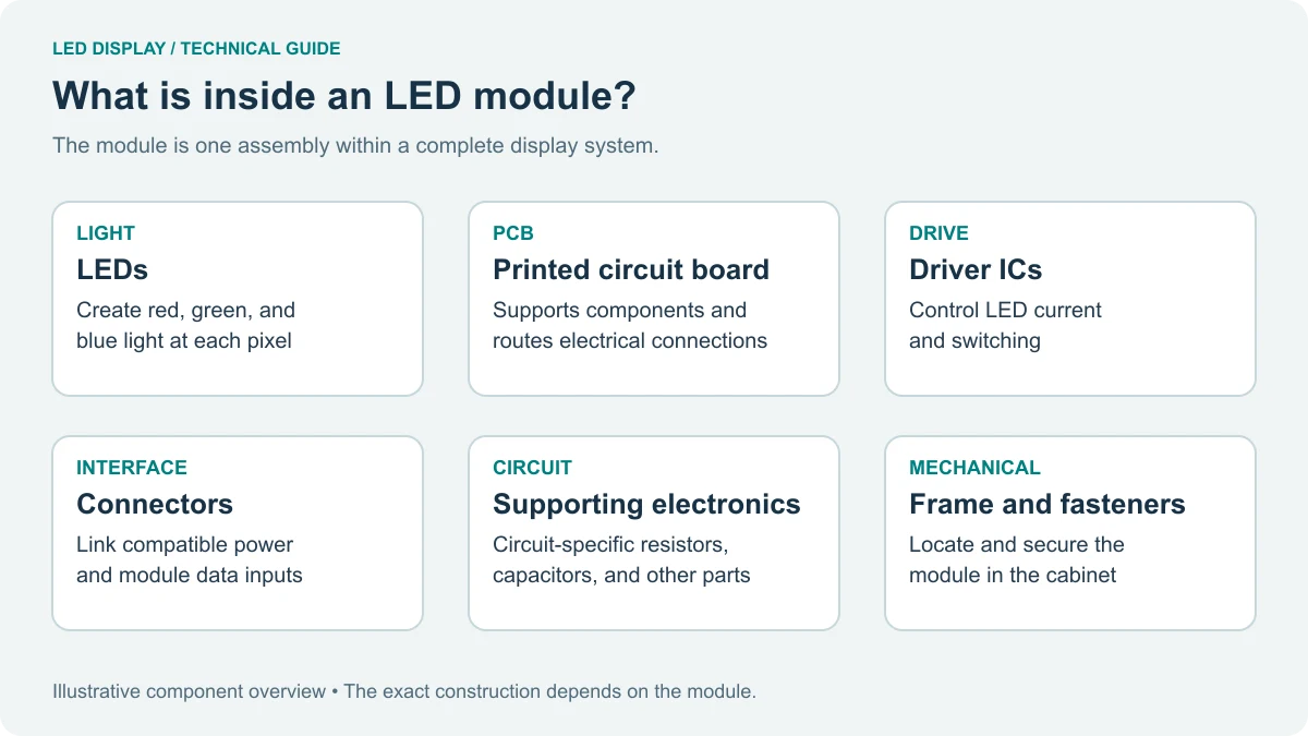
01. Receiver outputs and HUB connections
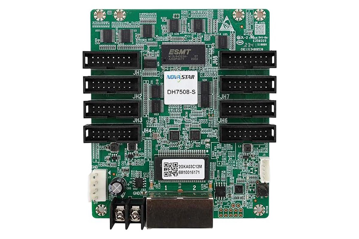
A HUB board routes module connections from the receiving hardware. Some receiving cards integrate the output headers instead. The correct module configuration includes more than width and height: scan arrangement, data grouping, driver compatibility, and output assignment can affect the displayed pattern.
Configuration naming is vendor-specific. Preserve the supplier-approved file and its associated hardware identification rather than copying parameters from a visually similar screen. The receiving card guide covers receiver selection and cabinet compatibility in more detail.
02. Drivers turn data into controlled light
Driver circuits control LED current and switching. Many designs use pulse-width modulation and scanning to produce brightness levels across groups of pixels. Refresh behavior therefore differs from source frame rate: repeated light-output updates do not create additional unique video frames.
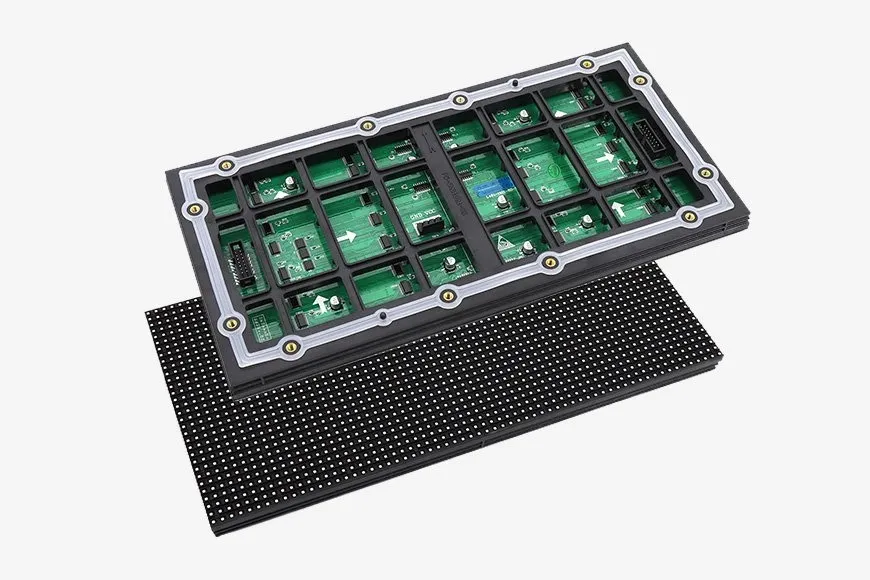
When tracing LED display signal flow, a correct image in one cabinet confirms only the tested path and settings. Other cabinets may have different configuration data or a local connection problem. Compare recorded hardware identifiers before treating every visually similar module as equivalent.
5. Map an Eight-Cabinet Wall: A Worked Example
Pixel mapping links logical image regions to physical cabinet positions. To make LED display signal flow reviewable, define the audience’s front view as the reference. Put the origin at the upper-left corner, with x increasing rightward and y increasing downward.
01. Assign a region to each cabinet
For our 768 × 384 wall, the top-row cabinet origins are (0,0), (192,0), (384,0), and (576,0). The lower row uses the same x coordinates with y=192. Cabinet A covers x=0 through 191 and y=0 through 191. Its neighbor begins at x=192, so the regions touch without overlap.
02. Connection order is not screen position
Suppose the physical data chain runs A → B → C → D → H → G → F → E. The lower row is visited right to left, although its picture still reads normally left to right. The connection map must associate that chain order with the proper coordinates. Reversing the lower-row coordinates can produce swapped image regions even when every receiver communicates.
The example contains 294,912 pixels: eight multiplied by 192 multiplied by 192. That total alone does not approve a single-port design. Check the actual sender’s and receivers’ limits under the chosen frame rate and operating mode. If multiple outputs are required, divide the route and document the start position and load for each output.
03. Validate with identifiable content
Use a test image labeling each cabinet A through H, with arrows indicating up and right. Add a border around the whole canvas and lines across cabinet boundaries. This exposes swapped regions, incorrect orientation, missing edges, and offsets more clearly than a moving promotional video. Record the expected map alongside a front-view photograph of the result.
6. Separate Signal Connections From Power Distribution
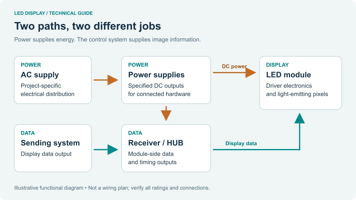
LED display signal flow carries image information. The power system supplies operating energy to the display electronics. A communicating receiver does not prove that every module has its required supply, and an illuminated status indicator does not establish correct voltage under load.
01. Keep two coordinated drawings
The signal drawing should identify image paths and configuration boundaries. The electrical drawing should identify supply ratings, protective devices, distribution, and loads. Use matching cabinet identifiers on both. A technician can then relate a dark area to its data chain and its supply circuit without assuming that the two routes are identical.
Supply voltage is model-specific. Do not infer it from cabinet dimensions, pixel pitch, or connector appearance. Internal electrical measurements and changes belong to qualified personnel following the equipment procedures. This article provides a functional model, not installation wiring instructions.
02. Preserve the distinction during diagnosis
A dark downstream group can suggest a data-chain interruption, but it can also share a failed power circuit. Conversely, a wrong image region often points toward mapping while still requiring verification. Treat visible symptoms as clues and compare them with the two drawings before replacing components.
7. Check Port Loading and Processing Tradeoffs
A complete LED display signal flow review checks several limits separately: input acceptance, processing canvas, total output load, load per output, and load per receiving card. A controller’s headline pixel capacity cannot answer all five questions.
01. Check the operating conditions behind capacity
Request the supported configuration at the intended frame rate, bit depth, and enabled features. Some devices change their supported load or modes when settings change. Receiver output groups and module scan requirements also matter. Ask the supplier to identify the applicable manual revision and the tested configuration rather than supplying a generic maximum.
Apply those limits to the worked map before choosing a cable route. Check each output’s allocated pixels and each receiver’s region. Leave documented allowance for any planned expansion; do not call unused headline capacity available until the proposed additional width, height, and outputs are supported.
02. Compare integration, flexibility, and recovery
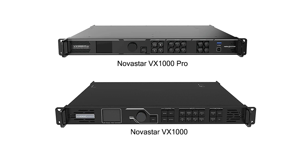
An integrated processor and sender can reduce inter-box connections. Separate devices can offer a different mix of inputs, processing, or service options. Neither arrangement guarantees lower latency or simpler recovery. Evaluate the actual functions required and how a failed unit would be replaced.
For live events, test the complete source-to-screen delay in the intended mode. For scheduled signage, test restart behavior and local playback. For either use, a backup connection is useful only when the hardware supports it, the configuration enables it, and a controlled interruption demonstrates the expected recovery.
8. Trace Display Faults Without Losing the Evidence
Follow LED display signal flow from known checkpoints instead of changing several settings at once. Record the source, input status, affected area, recent changes, and test pattern used. Save the current configuration before an authorized change and keep the last verified backup separate.
01. Understand what each test actually proves
A processor-generated pattern may bypass the external video source. A receiver-generated pattern may bypass additional upstream stages. Check the manual to learn where the pattern originates. A successful local pattern can narrow the investigation, but it does not validate a cable or processing stage that the test bypassed.
| Observation | What it helps establish | What remains unproven |
|---|---|---|
| Controller detects input timing | A source signal reaches that input | Correct scaling, output map, and module operation |
| Internal pattern displays correctly | The tested downstream stages operate in that mode | Any upstream stages bypassed by the pattern |
| Cabinet labels appear in wrong positions | Regions are visible but their assignment needs review | The exact error until coordinates and chain order are compared |
| Several adjacent cabinets are dark | The fault affects a defined physical region | Whether the cause is power, data, configuration, or hardware |
| Problem returns after restart | The operating state is not reliably restored | Whether saving, startup selection, or another dependency is responsible |
02. Change one variable and record the outcome
Use the supplier’s procedure and a known compatible replacement when substitution is appropriate. Record which cable, setting, or component changed and whether the symptom moved. Changing module parameters merely to make an image look better can conceal the original fault and make recovery harder.
9. Verify the Configuration Before Handover
Commissioning should demonstrate LED display signal flow under the conditions the operator will use. Agree on a defined source, canvas, brightness setting, test content, and restart sequence. For camera work, include the intended frame rate and shutter settings because a refresh specification alone cannot predict the filmed result.
01. Confirm geometry, content, and recovery
First verify the labeled cabinet pattern and full-frame border. Then show representative slides, moving content, and dark gradients. Confirm that scaling preserves the intended content and that configuration remains correct after the approved save and restart procedure. Where supported, test the agreed backup behavior separately.
02. Hand over files that match the installed wall
Collect the final cabinet map, port allocation, module configuration, calibration records, hardware list, software versions, and recovery instructions. Label their revision and the tested installation. Store access details through the project’s normal secure handover process. A folder of unexplained files is difficult to use during an outage.
Ask the supplier to show how the saved configuration relates to the physical cabinet identifiers. This turns the LED display signal flow diagram into a working service document. Record any untested feature explicitly so the operator does not mistake a quoted capability for an accepted one.
FAQ
Does the configuration computer need to remain connected?
That depends on its role. A computer used only for setup may be removable after the supported save procedure. If the same computer supplies live video or runs playback software, disconnecting it can remove the content source. Verify both roles before unplugging it.
Can a 4K video file play on a smaller LED canvas?
Potentially, if the player and processing chain support the file and required scaling. File decoding, input acceptance, and physical pixel resolution are separate limits. Test the actual codec, timing, and content instead of relying only on the file’s resolution label.
Does adding more output cables reduce video delay?
Not automatically. Additional outputs distribute the display load but do not necessarily change buffering or processing latency. Use the manufacturer’s supported mode and measure the complete path if timing matters for live cameras, presenters, or synchronized playback.
Can two receiving-card ports always be used as a backup?
No. The presence of two ports does not establish the supported redundancy arrangement. Check the sender, receiver, software configuration, and documented topology together. Test failover before relying on it during an event or unattended operation.
Should a replacement receiver use the newest firmware?
Use the version approved for the installed system. A newer release may have different compatibility requirements or behavior. Preserve the working configuration and ask the supplier to specify the replacement procedure, firmware version, and verification tests.
Conclusion
Accurate LED display signal flow documentation connects the source format, interface roles, cabinet coordinates, output loading, and module configuration. Keep the power drawing alongside it, and verify each boundary with a test whose scope is understood.
For an EagerLED configuration review, send your cabinet pixel dimensions, wall arrangement, source timing, required playback workflow, and proposed connection map through our project inquiry page. Request a matched layout and a documented commissioning demonstration before accepting the system.
 Outdoor LED Mesh Screen: Rigid Cabinet or Flexible Curtain?