
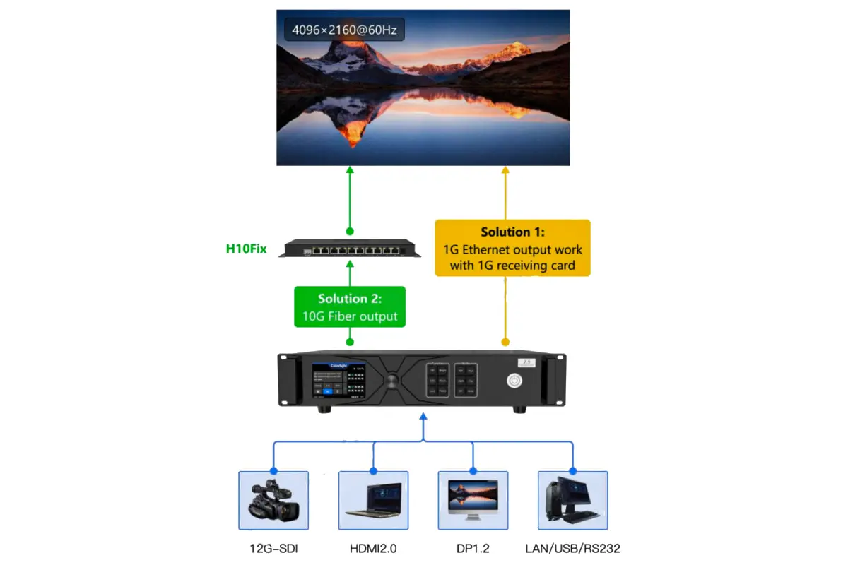
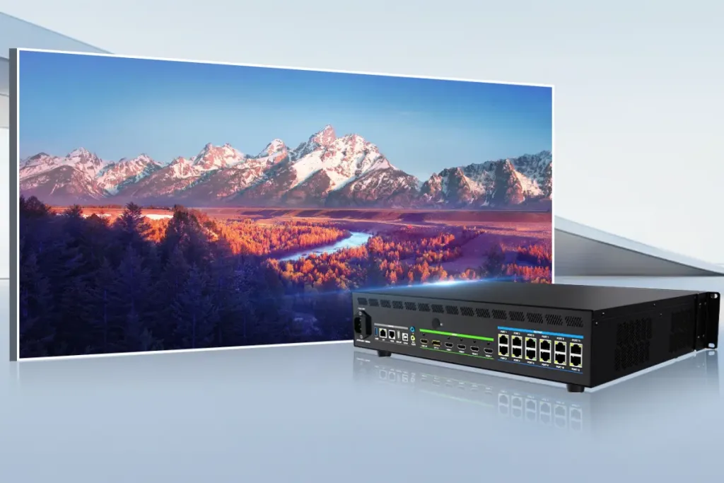
Colorlight Z5 is a 4K LED video controller that combines video processing with LED sending functions. It accepts HDMI 2.0, DisplayPort 1.2 and 12G-SDI directly, then drives compatible receiving cards through 20 Gigabit Ethernet outputs or two 10G fiber outputs. Start a project by matching the input format, output pixel budget and cabinet wiring.
This Colorlight Z5 guide is for rental technicians, AV integrators and buyers planning stage or fixed LED walls. It explains the specifications that affect purchasing, a practical setup sequence, camera testing and fault isolation. The numerical limits below come from Colorlight’s Z5 Product Specification V2.0; software steps follow the Z5 User Manual V1.0. Examples are planning calculations, not measured installation results.
Before connecting: video enters the video inputs; USB and LAN are control connections. Fiber outputs mirror groups of Ethernet outputs and do not add an independent pixel canvas. Higher output frame rates and bit depth reduce capacity. Confirm hardware and firmware compatibility before relying on a maximum value.
1. Colorlight Z5 Specifications and System Role
The Colorlight Z5 sits between the video source and the LED receiving system. A media server, presentation computer or switcher supplies video. The Colorlight Z5 crops, scales or arranges the selected sources, and sends mapped pixels to the cabinets. A separate sending card is not required simply to feed HDMI video into this controller.
The Colorlight Z5 is also different from an asynchronous advertising player: its USB Type-B port manages device parameters, rather than serving as a normal video input or USB-stick playback port. Keep content creation and playback on the source equipment. For background on the components, see our LED control system guide.
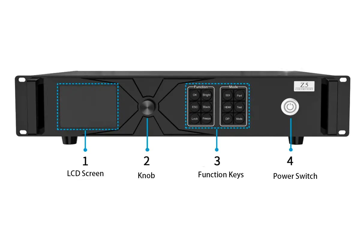
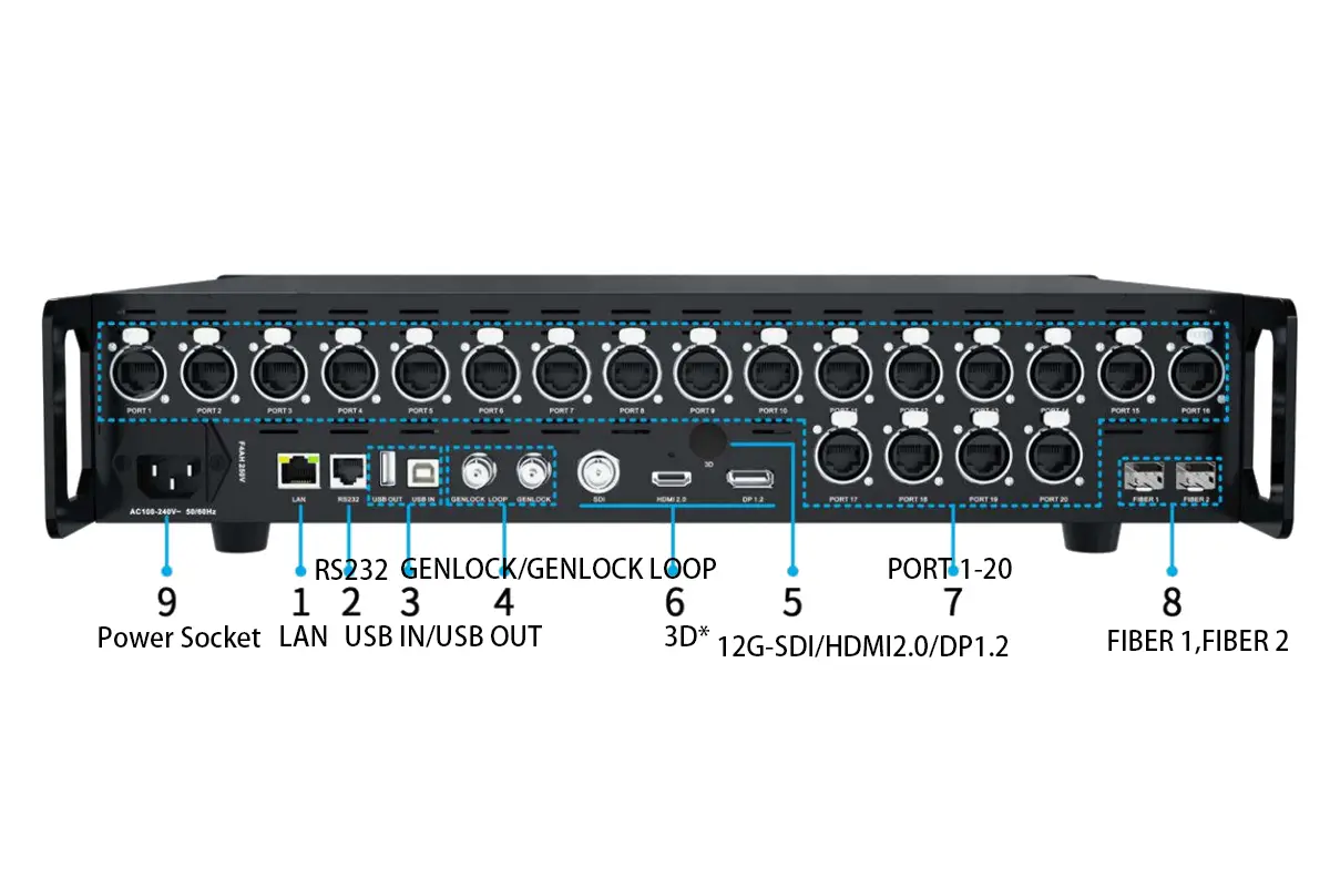
01. Verified interface and hardware specifications
On small screens, swipe horizontally to view all columns.
| Item | Z5 specification | Planning implication |
|---|---|---|
| Video inputs | 1 × HDMI 2.0, 1 × DP 1.2, 1 × 12G-SDI; up to 4096 × 2160 at 60Hz | Check the supported sampling, bit depth and frame rate for the chosen connector. |
| LED outputs | 20 × Gigabit Ethernet; 2 × 10G fiber | Choose Ethernet or fiber output mode; fiber modules are optional. |
| Maximum output geometry | Up to 16,384 pixels wide or 8,192 pixels high in Specification V2.0 | Width, height and total pixel limits must all be satisfied. |
| Video processing | Cropping, scaling, switching and up to 3 windows | Prepare window positions and source formats before show rehearsal. |
| Synchronization | Genlock input and loop; bi-level/tri-level, 23.98–60Hz reference | Verify the reference format separately from video input capability. |
| Chassis and power | 2U; 482.6 × 88.0 × 407.1mm; 75W rated power; AC 100–240V, 50/60Hz | Allow suitable rack depth, grounding and ventilation. |
| Operating conditions | −20°C to 55°C; 0–90% RH, non-condensing | Protect the controller from liquid and condensation. |
Source: Colorlight Z5 Specification V2.0, interfaces, features and device specifications. The older user manual has different aggregate capacity and width figures. Use the newer specification for this table, then confirm the limits shown by the actual unit and its firmware. Do not combine a headline width with a headline height and assume their product is supported.
02. Separate input resolution from screen resolution
A 3840 × 2160 source contains 8,294,400 pixels. Your LED wall may have a different native canvas, so the Colorlight Z5 must crop or scale the source appropriately. Select whether the installation should preserve the whole image with borders, fill the wall by cropping, or use content authored for its native aspect ratio. Scaling cannot create physical LED pixels that are absent from the cabinets.
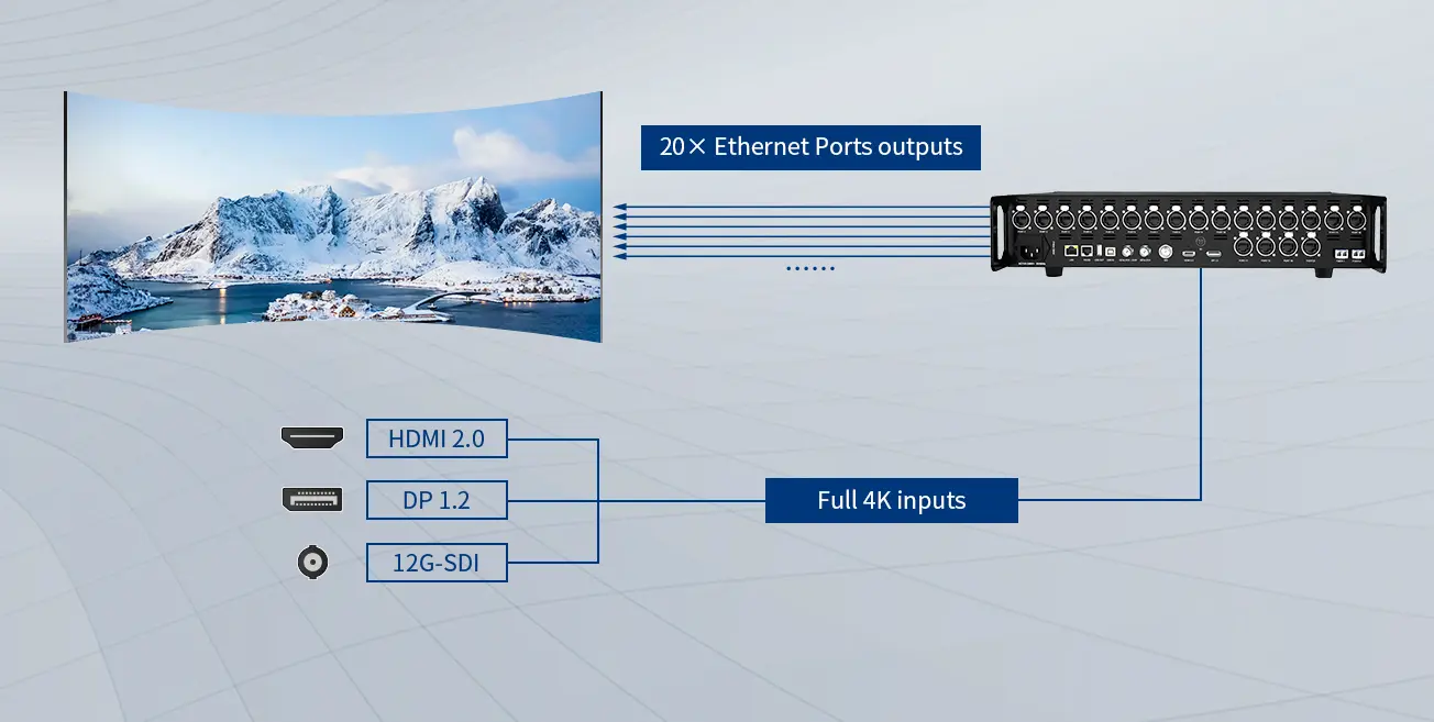
2. Plan Pixel Capacity and Output Connections
Size the Colorlight Z5 using both total output load and the busiest individual port. Cabinet quantity alone is insufficient because two cabinets with identical physical dimensions can contain very different pixel counts. Receiving-card limits, scan configuration, the selected mode and the backup topology also constrain a working design.
01. Compare output modes before allocating ports
On small screens, swipe horizontally to view all columns.
| Output mode | Device total in V2.0 | Per Ethernet port in V2.0 | Practical consequence |
|---|---|---|---|
| 60Hz, 8-bit | 13.10 million pixels | 650,000 pixels | Provides the largest listed capacity among these four modes. |
| 60Hz, 10-bit | 9.83 million pixels | 490,000 pixels | Recalculate every port when moving from 8-bit to 10-bit. |
| 120Hz, 8-bit | 6.55 million pixels | 320,000 pixels | Higher frame rate reduces the available pixel budget. |
| 120Hz, 10-bit | 4.91 million pixels | 240,000 pixels | Large canvases may need more controllers or a different design. |
These published values are rounded independently. For Colorlight Z5 planning, satisfy each limit separately rather than using the device total divided by 20 as a new per-port rating. A source-format table is a separate constraint: support for high frame rates at selected resolutions does not mean 4K input at every listed frame rate.
02. Work through a cabinet calculation
Consider an illustrative wall with 12 columns and 6 rows of 256 × 256-pixel cabinets. Its native canvas is 3072 × 1536, or 4,718,592 pixels across 72 cabinets. At 60Hz and 8-bit, eight cabinets on one output contain 524,288 pixels; nine such chains fit the published 650,000-pixel port ceiling, subject to receiving-card compatibility and routing.
At 60Hz and 10-bit, the same eight-cabinet chain exceeds 490,000 pixels. Six cabinets contain 393,216 pixels, so twelve six-cabinet chains are a possible starting layout. At 120Hz and 10-bit, three cabinets contain 196,608 pixels but would require 24 chains. That exceeds the Colorlight Z5’s 20 Ethernet outputs, although the wall is below the rounded device-total figure. This is why a total-only calculation can approve an unusable port map.
03. Plan copper and fiber as alternative output paths
FIBER 1 corresponds to PORT 1–10; FIBER 2 corresponds to PORT 11–20. The Colorlight Z5 specification requires choosing Ethernet or fiber output mode. Fiber operation needs suitable modules and compatible receiving or conversion equipment; its distance depends on the optical module specification. Document the full route and connector type before ordering. Do not treat the two fiber ports as additional independent screen capacity.
3. Set Up the Controller with iSet
The Colorlight Z5 User Manual V1.0 specifies iSet 6.0 or later. Use a manufacturer-approved release compatible with the controller and receiving cards. Our Colorlight software guide helps distinguish configuration tools; obtain installation packages and firmware from official support.
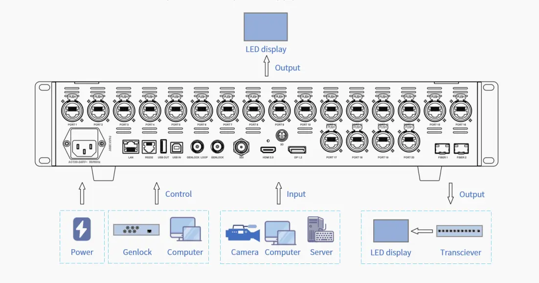
01. Connect video, control and LED outputs
- Record cabinet pixel dimensions, receiving-card models, physical arrangement and cable order. Obtain the approved cabinet configuration from the screen supplier.
- With equipment prepared according to its manuals, connect the source to HDMI, DP or SDI. Connect USB IN to the setup computer, or use the LAN control connection.
- Connect the chosen LED output route to the receiving system. Label the controller output and the first cabinet in each chain.
- Apply power using the manufacturer’s connection sequence and a properly grounded supply. Keep the processor protected from moisture.
- Open iSet and detect the device. Compare detected receiving-card counts against the physical wiring before adjusting the image.
If iSet cannot find the Colorlight Z5, first inspect the control cable, driver and computer connection. If the controller appears but some receiving cards are missing, inspect the corresponding output chain. These are different faults; changing video resolution will not repair a broken control connection.
02. Set the canvas, source and windows
In the video-source controls, check the resolution and frame rate actually received by the Colorlight Z5. Set the output frame rate and bit depth to the planned mode. Define the native screen canvas, add the source window, and set its position and dimensions. The manual documents up to three windows; confirm any processing restrictions for the selected operating mode.
For HDMI or DP, EDID tells the source which signal formats to offer. Use a compatible preset first. Only create a custom timing after confirming source and controller support. SDI does not use the same EDID setup. If an image is cropped or stretched, inspect the source window and crop settings before changing the cabinet map.
03. Map receiving cards and preserve the working configuration
In iSet Layout, select a sending port, add cabinets with the correct resolution and assign their connection order to match the cables. Repeat for every active port, then use the documented save-connection function. Test a numbered grid to catch reversed rows, duplicated regions and offset cabinets that a uniform white image would hide.
For each Colorlight Z5 project, keep the approved cabinet configuration, layout record and controller settings together. Save a named configuration using the format supported by the installed software; do not assume an arbitrary file extension is universal. After a controlled power cycle, verify that the screen restores the intended layout and operating mode.
4. Adjust HDR, Color and Camera Synchronization
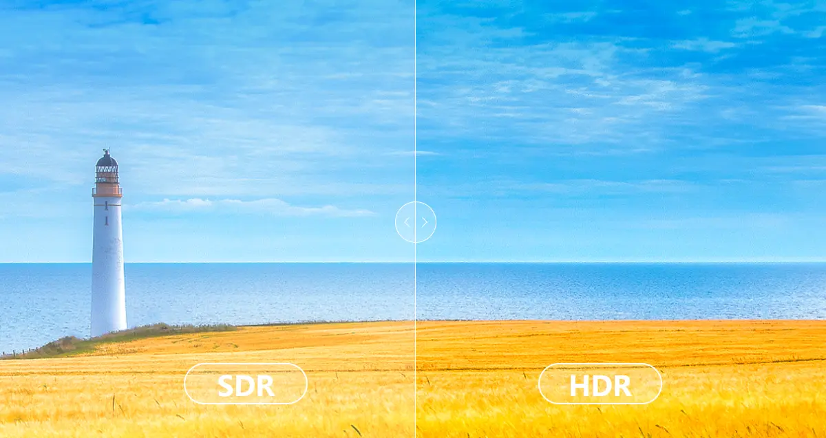
The Colorlight Z5 can process HDR10 and HLG, but HDR is a complete signal-chain decision. The source encoding, connector format, receiving card and panel must work together. A Colorlight Z5 setting alone cannot guarantee higher visible contrast or correct color on every screen.
01. Establish SDR and HDR reference settings
The official manual documents HDR on HDMI and DP and specifies i9 or above receiving cards for HDR and advanced color functions. Confirm the exact receiving-card and firmware combination with Colorlight. Begin with a known SDR reference, then introduce HDR content and the matching processing mode. Use grayscale ramps, skin tones and highlight detail to assess the change.
When commissioning the Colorlight Z5, match full-range or limited-range video handling across the source and processor. Crushed blacks and washed-out images can result from range mismatch, not defective LED modules. Avoid compensating with extreme brightness or gamma adjustments before checking the signal interpretation. See our LED display HDR explanation for the distinction between processing support and panel performance.
02. Distinguish frame rate, LED refresh and Genlock
Video frame rate describes incoming or outgoing images per second. LED refresh behavior is also affected by receiving cards, driver ICs and scan settings. Genlock aligns timing to a reference. These terms are related, but setting 60Hz video does not specify the LED module’s refresh rate, and Genlock does not automatically remove all camera banding.
The Colorlight Z5 offers external Genlock and other synchronization choices documented in iSet. For a broadcast system, agree on a reference format with the video engineer, confirm lock, then test the actual cameras at their intended shutter settings and brightness levels. Film motion and low-gray scenes as well as white patterns. A clean result on one camera is not proof for every camera or shutter combination.
03. Measure latency across the complete chain
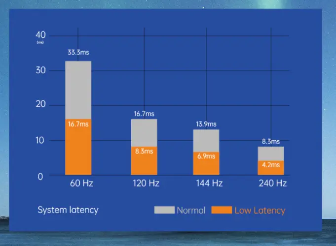
Colorlight Z5 Specification V2.0 lists low-latency and zero-frame processing features. Treat these as processor-mode capabilities, not an unconditional claim of zero camera-to-screen delay. Cameras, switchers, scaling, transport and receiving hardware can contribute additional delay. Verify which features remain available in the selected latency mode.
At 60 frames per second, one video frame is approximately 16.7ms. Use that conversion to interpret a measured delay, not to invent a measured result. For live image magnification, compare a common visible timing reference on the source monitor and LED wall, then assess audio alignment with the production team.
5. Match the Workflow to Acceptance Tests
A Colorlight Z5 deployment should be chosen around the show workflow. A touring wall needs repeatable mapping and rapid recovery; a corporate presentation may prioritize readable graphics and color consistency. The same hardware can serve both, but the acceptance checks should differ.
On small screens, swipe horizontally to view all columns.
| Use case | Main concern | Test before acceptance |
|---|---|---|
| Touring rental | Cabinets and cable order change between venues | Rebuild the recorded layout, check cabinet IDs and restore the approved configuration. |
| Broadcast or live cameras | Timing, banding and visible delay | Test house reference, camera shutters, motion and grayscale using production equipment. |
| Corporate presentations | Text clarity and predictable source switching | Check native-resolution graphics, small text and each presenter input. |
| Fixed installation | Recovery after power loss and serviceability | Power-cycle in a maintenance window and verify the documented restart process. |
For a Colorlight Z5 system used with a media server, treat the server's output as a standard compatible video signal. Software brand names do not prove integration: check the actual output timing, sampling and connector path. Prepare a simple fallback source so a content-computer fault can be isolated without remapping the wall.
Outdoor screen applications do not make the controller weatherproof. The Colorlight Z5 manual says it is not waterproof. Locate it in suitable protected equipment space, separate its environmental requirements from the LED cabinet rating, and plan access for the operator throughout the event.
6. Commission, Back Up and Operate the System
Commission the Colorlight Z5 as a complete system before the audience arrives. A successful Colorlight Z5 test pattern proves only part of the path. The final content, source switching, saved configuration and recovery process all need their own checks.
01. Run a repeatable acceptance sequence
- Check a numbered cabinet grid against the wiring drawing.
- Display red, green, blue, white and grayscale patterns at the planned operating brightness.
- Play final-resolution graphics and motion clips from every required input.
- Test the production camera and synchronization combination where applicable.
- Confirm the correct settings return after an approved restart.
- Record the result, configuration version and any remaining limitations.
Do not increase a receiving-card scan or refresh setting simply because a higher number is available. Use the cabinet supplier's approved configuration and check temperature, grayscale and stability. For context on those dependencies, consult the LED receiving-card guide.
02. Test redundancy as an actual failure scenario
The Colorlight Z5 specification lists port backup and multi-device redundancy. Those features still require a compatible topology and configuration. Define whether the design protects against a source fault, cable fault or controller failure. A second processor sharing the same failing source or power route may not protect the event against that fault.
During rehearsal, simulate only the agreed failure conditions and record the visible result and recovery procedure. Do not promise seamless failover until that specific system has demonstrated it. A Colorlight Z5 backup plan should identify the person authorized to switch, the fallback content and the steps needed to restore normal operation.
03. Keep show operation predictable
Use the front-panel lock to reduce accidental changes after setup. Make operators familiar with Black, Freeze, input selection and preset controls. A black screen may be an intentional output state rather than a disconnected source. Keep the known-good settings accessible, and schedule firmware changes for a maintenance window with time to retest.
7. Troubleshoot the LED Wall by Symptom
Troubleshoot the Colorlight Z5 in signal order: source, input lock, processing state, output mode, cable chain and receiving cards. Change one variable at a time and record whether the symptom follows a cable, port or cabinet. This prevents a recoverable local fault from turning into a complete remapping exercise.
On small screens, swipe horizontally to view all columns.
| Symptom | Check first | Next useful action |
|---|---|---|
| Entire wall is black | Source lock, selected input, Black state and power | Try a known-good input and internal test pattern to separate input from output faults. |
| iSet cannot detect the controller | USB/LAN control path and driver | Verify the computer connection independently of the video cable. |
| One output chain is dark | First cabinet power, cable and output selection | Inspect the first failed point and compare detected cards with the wiring drawing. |
| Image repeated, shifted or scrambled | Cabinet dimensions and connection order | Use a numbered grid; correct the map against the physical cable sequence. |
| Picture stretched or cropped | Canvas, source crop and window dimensions | Restore the agreed aspect-ratio policy before changing receiving-card settings. |
| Gray image or crushed blacks | Video range and HDR/SDR interpretation | Test a reference ramp and remove conflicting transformations. |
| Camera bands or rolling lines | Camera shutter, panel settings and synchronization | Retest the full camera/LED combination at production brightness. |
01. Isolate the smallest reproducible problem
If one section fails, compare it with a working chain before resetting the Colorlight Z5. A test pattern that displays correctly while external video fails points toward source selection or processing. A fault visible on both test patterns and video suggests a later part of the path, though cabinet configuration still needs checking.
02. Escalate with useful evidence
Send support the controller model, firmware, iSet version, receiving-card model, selected input format, output mode and port map. Add photographs of the symptom and the exact steps that reproduce it. State what changed before the fault. A concise record is more useful than a general claim that the Colorlight Z5 is unstable.
8. Buying Checklist and Project Handover
Before buying a Colorlight Z5, request a system proposal based on native pixels and the intended output mode. Include the source interfaces, cable distances, cabinet arrangement, receiving-card models, camera requirements and backup expectations. Ask the supplier to confirm the busiest port as well as the total screen load.
Check the supplied optical modules, compatible conversion equipment, rack space and support scope. Obtain the current manual and firmware compatibility guidance; the published V2.0 specification and older V1.0 manual contain differences, so a purchase should identify which limits apply to the delivered hardware. Avoid treating a copied specification from another controller as equivalent.
The Colorlight Z5 handover package should contain an as-built signal diagram, labeled port map, configuration backups, approved source timings and restart instructions. Include the tested camera settings and backup procedure where applicable. To request a matched screen-and-control proposal, send the EagerLED team your pixel dimensions and project requirements.
9. Colorlight Z5 FAQ
01. Does the Colorlight Z5 accept HDMI directly?
Yes. The Colorlight Z5 has a built-in HDMI 2.0 input, a DP 1.2 input and a 12G-SDI input. USB IN is for computer control or cascading, not the normal video-source connection. A separate sending card is not required just to connect an HDMI source.
02. How many Ethernet outputs does the Colorlight Z5 have?
The Colorlight Z5 has 20 Gigabit Ethernet outputs. Its two 10G fiber outputs correspond to groups of ten Ethernet outputs. The specification requires selecting Ethernet or fiber mode; fiber does not create an additional independent pixel budget.
03. Which software should I use for Colorlight Z5 setup?
The official Z5 User Manual V1.0 specifies iSet 6.0 or later. Choose a release approved for your hardware and firmware. Use it to detect devices, set source windows and map receiving cards, then save the connection relationships and keep a project backup.
04. Can the Colorlight Z5 drive every 4K wall at 120Hz?
No. Output capacity depends on frame rate and bit depth. At 120Hz and 10-bit, V2.0 lists 4.91 million pixels total and 240,000 per Ethernet port. A 3840 × 2160 wall contains 8,294,400 pixels, exceeding that total. Input timing must also be supported separately.
05. Does Genlock guarantee a flicker-free camera image?
No. Genlock aligns timing, while camera artifacts also depend on shutter settings, LED scan behavior, refresh configuration and brightness. Test the actual cameras and cabinets. Processor latency specifications also do not describe total camera-to-screen delay.
06. What receiving cards are required for HDR?
The Colorlight Z5 manual specifies i9 or above receiving cards for HDR and advanced color functions and documents HDR10/HLG on HDMI and DP. Confirm the exact card and firmware combination, then test compatible HDR content on the installed panels.
 EagerLED Holiday Notice For NewYear's Day 2026
 Colorlight X8m vs X12m: Specs, Capacity and Setup Guide