

LED cabinet flatness describes how closely the faces of adjacent LED display cabinets sit in a common plane. A joint can look like a dark line because the cabinets are too far apart, their faces sit at different depths, or the pixels on either side emit different amounts of light. These faults can look similar from the audience area, so check the physical joint before changing the image settings.
For an AV integrator accepting an indoor video wall, the aim is to verify the installed screen against an agreed reference. Start with the cabinet drawing and supplier’s tolerances, then document what the wall looks like under repeatable conditions. That gives the installer and buyer a common basis for deciding whether a line needs adjustment.
1. What LED Cabinet Flatness Measures
Bowing within a single cabinet and a step between two cabinets are different measurements. A single cabinet might have a face that bows slightly across its width. Two individually flat cabinets can still meet at different depths if their mounting points are offset. A larger wall can also drift out of plane gradually even when each individual joint looks acceptable.
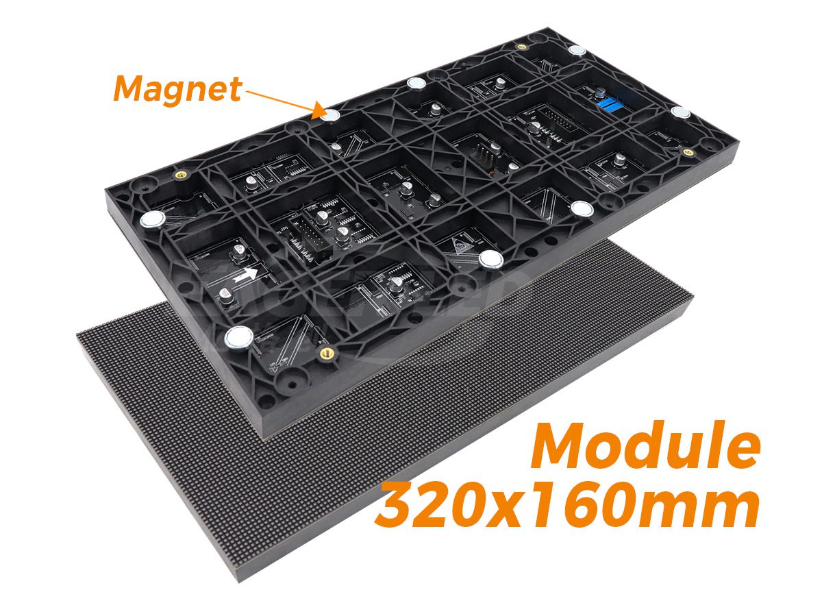
Start by distinguishing the cabinet-to-cabinet joint from the joint between removable modules inside a cabinet. Compare the cabinet drawing with the visible line. If the line follows the edge of one module while the neighboring cabinet joint looks uniform, the module seating or module itself needs attention. A repeating line along the full cabinet grid points to a different set of checks.
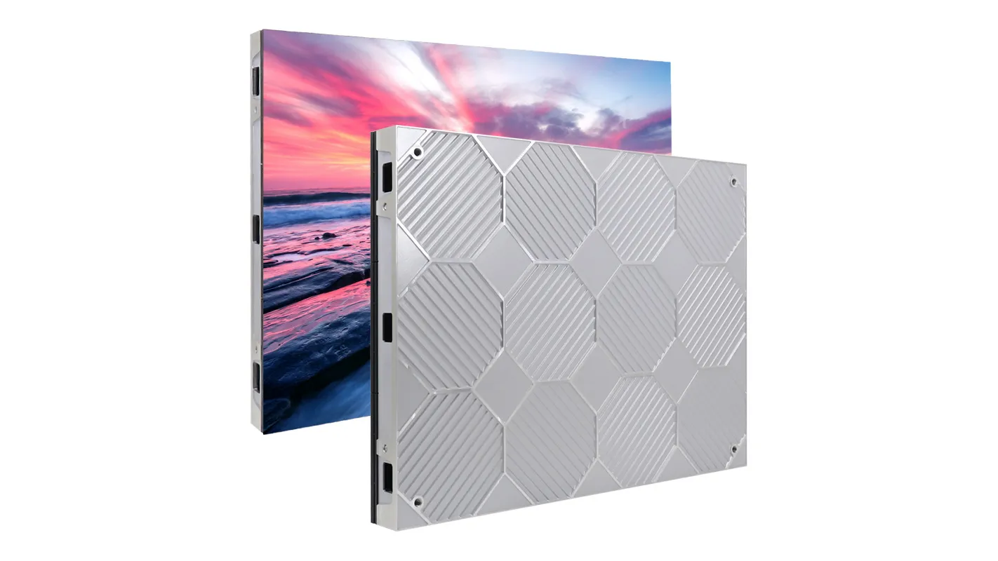
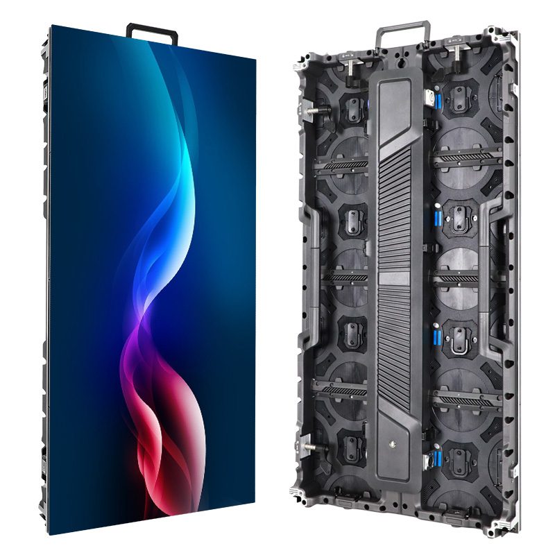
Ask the supplier which surface defines LED cabinet flatness for the quoted model. A drawing may refer to a machined frame surface, while the viewer sees the assembled LED face. The distinction matters when testing a sample with its modules removed. The EA640F2 cabinet and module images show why the frame and module interfaces should be discussed together.

A horizontal or vertical gap is another separate measurement. One cabinet can sit flush with the next while the spacing across the joint differs from the neighboring pixel spacing. Conversely, a narrow joint may still cast a visible shadow at an angle when the faces meet at different depths. Keep both observations in the inspection record.
2. Identify the Type of Seam
Look at the unlit surface under suitable room lighting, then repeat the check with the wall displaying a solid gray field. Inspect the wall head-on and from the agreed side viewing positions. Note whether the line is visible when the display is off, whether it changes with viewing angle, and whether it coincides with a physical boundary. These observations guide the next check without proving the cause by themselves.
For example, a line that appears to reverse from lighter to darker when viewed from opposite sides warrants a check for a depth step. A band that remains visible across the face of one module under the same test signal may point to brightness or color variation. Compare several gray levels before treating a single bright screen as sufficient evidence.
| What you see | What to check next | Evidence to keep |
|---|---|---|
| Visible opening at a joint with faces apparently flush | Cabinet spacing and alignment against the approved joint detail | Joint location, gap reading, and the reference used |
| Edge protrudes or recedes | Face depth on both sides and the condition of the support | Depth difference and which cabinet sits forward |
| Line follows one removable module | Module seating and physical condition with the cabinet boundary identified separately | Module position and photos before and after service |
| Gray test field shows a stripe without an obvious physical discontinuity | Output variation at several gray levels after checking the joint | Pattern, brightness preset, viewing position, and controller settings |
The LED wall test pattern guide explains how solid fields help isolate display faults. Use those patterns alongside the LED cabinet flatness inspection. Brightness correction can alter the appearance of a line, but it cannot move a cabinet face or remove a gap. Save the initial configuration so the team can compare before and after under the same conditions.
3. Agree on a Sample and Inspection Method
Ask to see several cabinets assembled together before approving a large order. A single powered cabinet can show image quality, but it does not show how the joints behave across a row or where four corners meet. A small array lets the parties agree on which seams to measure, where to stand, and which images to use. If the project uses multiple cabinet orientations, include the relevant orientation in the sample.
Translate LED cabinet flatness into a short inspection note. Record the reference surface, the maximum permitted deviation or step, the distance over which it is measured, and the tool approved by the supplier. Specify separate tolerances for the mounting plane and the assembled display where the design calls for them. Avoid placing an unprotected tool against exposed LED packages or assuming that a measurement method for one cabinet applies to another.
Consider two quotations that both promise a seamless finish. One supplies an assembled sample and defines a joint check at four-corner intersections. The other supplies a tolerance for a bare cabinet with no stated method for reviewing joints after installation. Those statements answer different questions. Ask both suppliers to define how the installed wall will be judged under the same room lighting, brightness setting, and viewing positions.
Include the mounting system in that conversation. A sample assembled on a factory fixture may behave differently from a wall mounted on the actual substrate. Ask how the approved structure accommodates deviations and who is responsible for checking it before cabinets are installed. If a tolerance can only be met by pulling a cabinet into position beyond its approved adjustment, bring the issue back to the installer and supplier.

4. Record the Installed Result
Mark cabinet rows and columns on a simple drawing so that both teams can locate a fault. Record LED cabinet flatness at the agreed positions, then repeat the visual review under the agreed viewing conditions. Under the same preset, take a front view, an oblique view where appropriate, and a close view of each flagged joint. Keep the photos paired with the measurements so that the team can reproduce the check.
Make sure the viewing positions reflect real use. A screen behind a reception desk may be seen close up and from a doorway at an angle. A meeting room wall may be evaluated primarily from seated positions. Inspect the mechanical joint where access is safe, and use the intended audience area to judge whether the finished image also meets the agreed visual standard.
For a disputed line, keep the order of checks consistent. Verify the location against the cabinet map, compare unlit and powered conditions, document the physical reading, then review the processor and calibration state. This makes it easier to tell which change helped and preserves a baseline if a later module replacement changes the look of that joint.
For handover, keep the accepted cabinet map, photos, approved measurements, and the applicable control preset together. If any location was accepted subject to a follow-up, write down exactly what needs to be rechecked and who will do it. The resulting LED cabinet flatness record can also help the service team find a seam again without repeating the entire inspection.
Choose the inspection points before the demonstration. Include joints near the perimeter, at least one intersection away from the edges, and any location where the support changes direction or type. Add other points if the agreed inspection plan calls for them. When two teams use different sampling positions, a comparison of their worst readings may say more about where they measured than about how the screen changed.
Also record whether the wall was cold, recently powered, or already operating in its normal state. If a seam appears only after the display has been running, record the time and operating conditions and ask the installation team to repeat the check under those same conditions.
5. Frequently Asked Questions
Is there one flatness tolerance for every indoor LED wall?
No. Use the limits specified for the cabinet and mounting system, and record the method and reference surface. A cabinet manufacturing tolerance cannot automatically serve as an acceptance limit for an assembled screen.
Can I approve the joints from a factory photograph?
A photograph is useful for documenting a sample, but camera position, exposure, and the pattern can hide a discontinuity. Request the measurements and conditions behind the photo, then repeat the agreed checks on the installed wall.
How should we inspect a wall designed with a curve?
Measure against the approved curved geometry and joint detail. Check the specified angles and transitions at the agreed positions. Applying a straight wall criterion across intentionally angled cabinets can misidentify a design feature as a defect.
Should we recheck a joint after a module is serviced?
Yes. Record the replacement module position and compare that joint with the handover photos. If a line appears only after the replacement, ask the service team to verify the fit and module compatibility before changing the wall-wide settings.
6. Prepare Your Indoor Wall Specification
Before signing off, compare the physical joint with the agreed tolerances and check the image from the intended viewing positions. Record the gap and depth readings separately, then save photos and the test settings alongside the cabinet map.
For an LED cabinet flatness review, share the proposed wall size, cabinet model, mounting arrangement, closest viewing position, and any seam acceptance criteria already in the project brief. Contact EagerLED about your indoor display project to request the applicable drawings and agree on what the sample and installation checks should cover.
 LED Wall Color Temperature: Is 6500 K Always Right?