
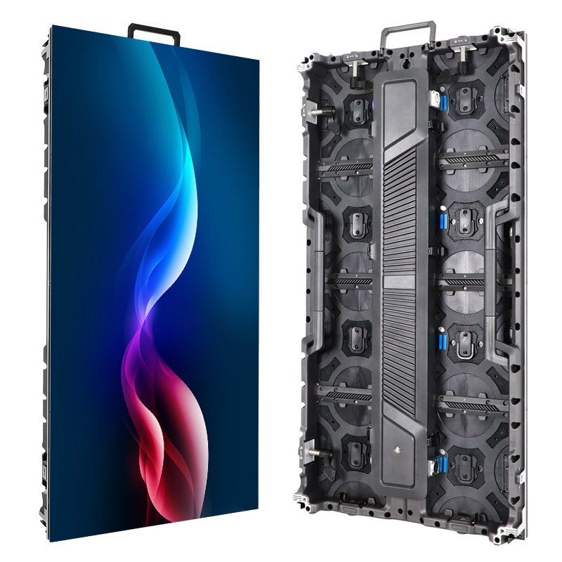
Before approving a curved LED wall, establish where the curve comes from: angled flat cabinets or a flexible emitting surface. This guide helps buyers interpret joint settings and request the drawing needed to check the real footprint.
1. Specify a smooth surface or an angled assembly
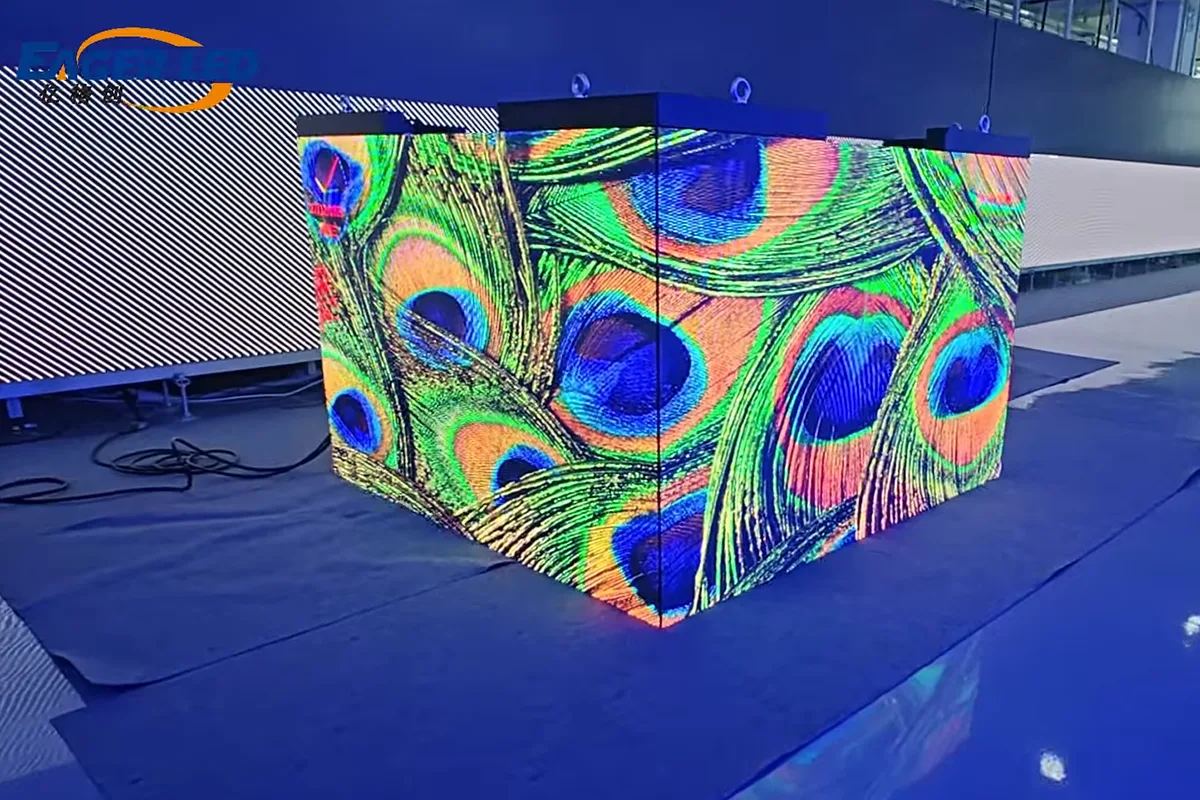
A curved LED wall can be made with flat cabinets joined at angles or with a display surface designed to bend. Both can form a curved overall layout, but they do not create identical surfaces.
Flat cabinets produce a series of planar faces. A flexible module can follow an approved curved support more continuously within its specified limits. Ask the supplier which construction is being quoted and request a plan view, not just a perspective rendering.
| Question | Angled flat cabinets | Flexible display surface |
|---|---|---|
| Where is the bend? | At approved cabinet joints | Across the approved flexible module and support |
| What drawing is needed? | Panel widths, joint angles and support layout | Module orientation, radius and support surface |
| What must be checked? | Facets, joins, hardware and content alignment | Allowed bending, alignment and component access |
| Is flexibility automatic? | No; curved locks may be optional | No; the model has limits and a mounting method |
2. A cabinet angle is a joint setting
On a cabinet-based curved wall, the angle normally describes the relationship between adjacent cabinets under the manufacturer’s convention. It does not state the total curve of an entire wall. Ask the supplier to mark the sign convention, intended viewing side and each joint setting on the drawing.
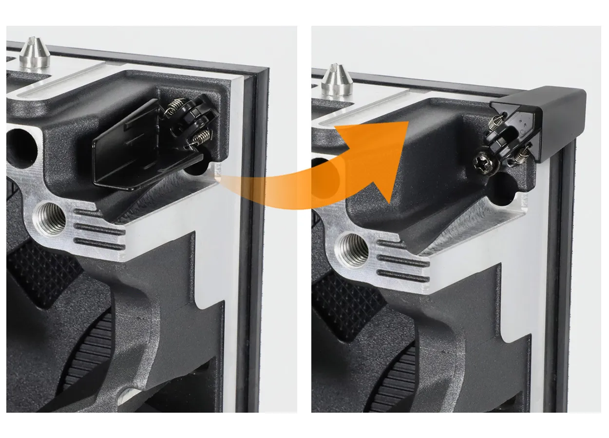
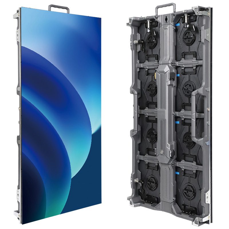
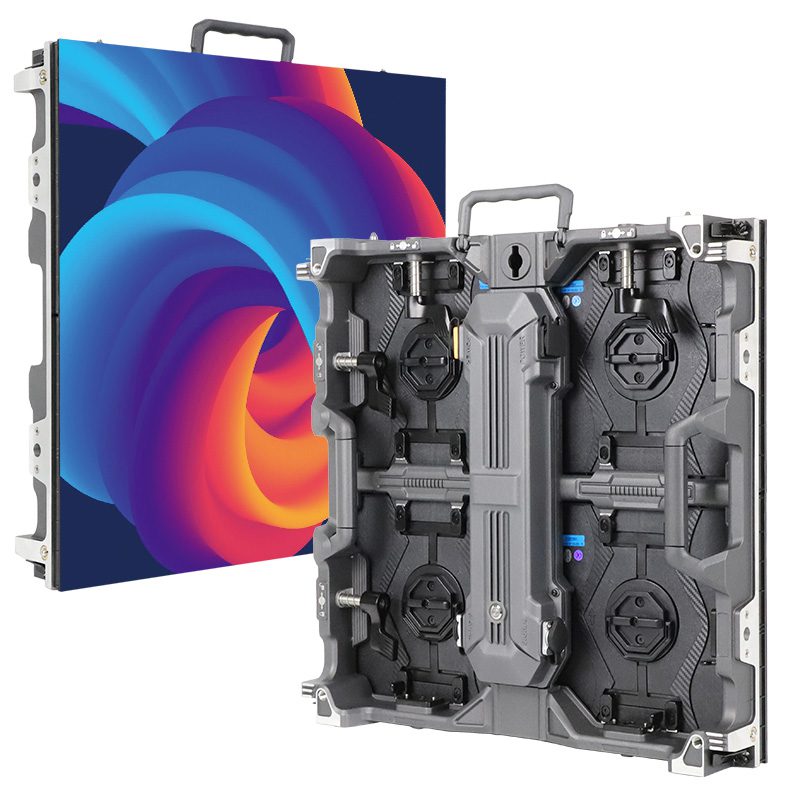
The EA500H9 rental cabinet offers optional curved-lock arrangements. Include those options in the order rather than assuming every stock cabinet has the required accessories. Confirm the approved settings and geometry for the supplied version.
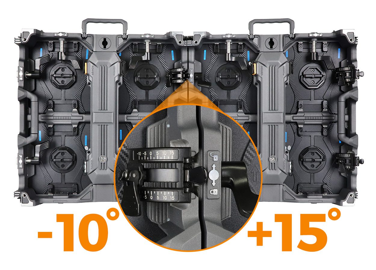
3. Eight cabinets do not mean eight internal joints
Consider a single row of eight flat cabinets. There are seven internal joins between the first and last cabinets. If each join turns the adjacent cabinet by the same hypothetical 5°, the first and last face orientations differ by 7 × 5° = 35°.
This is an explanation of joint counting, not an approved EA500H9 configuration or a complete circular-arc calculation. It does not establish a radius, support arrangement or safe installation. End fittings and any closing connection in a ring are separate parts of the design.
If the eight cabinets are nominally 500 mm wide, their summed face widths are 4 m. Once the faces are angled, 4 m is not automatically the straight-line width seen in the floor plan. Do not reserve stage space using the sum of cabinet widths alone.
4. Approve the plan-view footprint
Request a dimensioned plan showing the left-to-right span, the depth of the curved display, support or base footprint and the direction of the curve. Add the screen height in elevation. The drawing should show the actual emitting faces and the equipment behind them.
Mark audience locations, stage movement, camera positions, entrances and service routes. Have the responsible site team review the proposed footprint before fabrication or delivery. A curve that looks attractive in a rendering may occupy space needed for people or equipment.
For a flexible surface, obtain the approved radius and module orientation. For a cabinet assembly, obtain the panel sequence and angles. Do not convert one system’s curve description into the other system’s installation instructions.
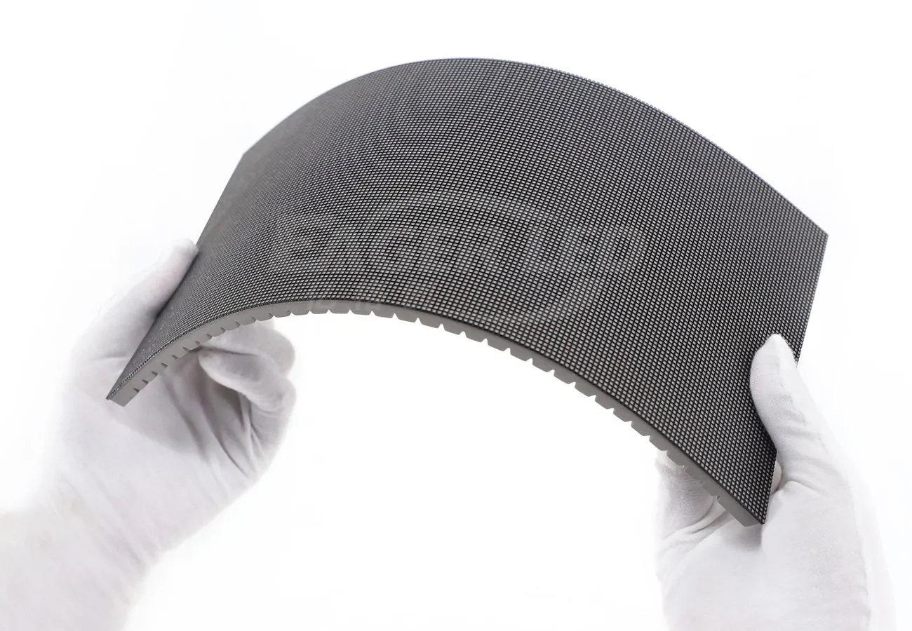
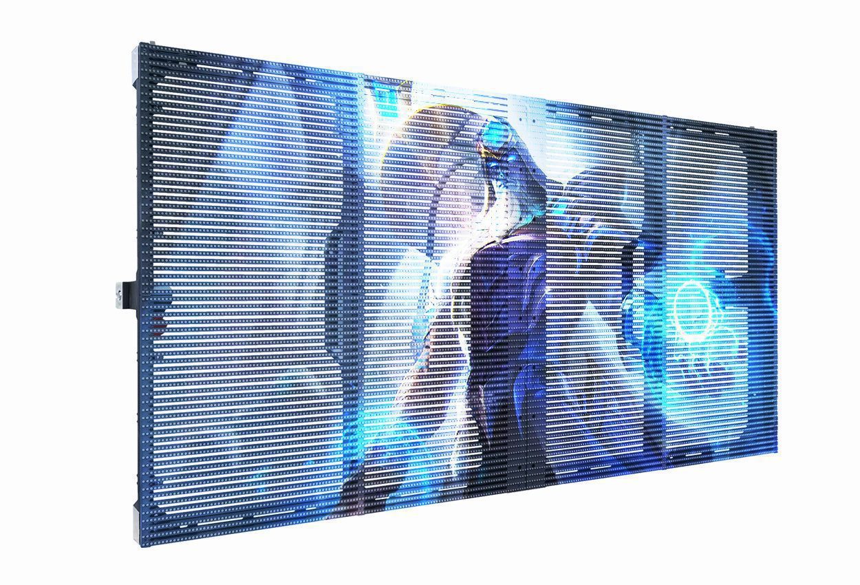
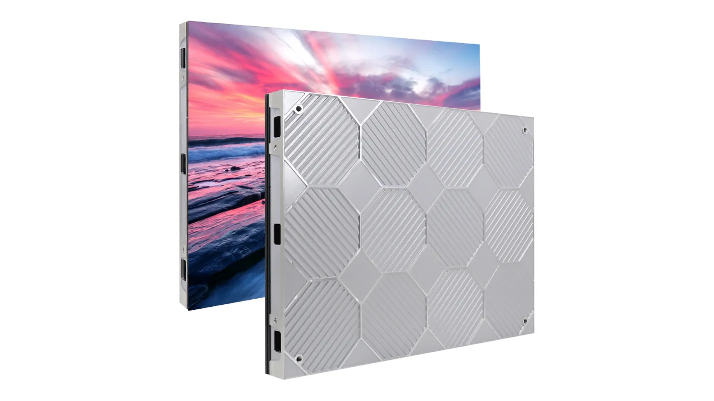
The EA-Flex indoor module range is one flexible-surface option. Do not transfer its indoor application or module specifications to an outdoor rental cabinet.
5. Compare artwork from the real audience positions
Prepare a test file with straight lines, a grid, a logo, short text and representative motion. Review it on the proposed geometry from the intended audience and camera positions. Record whether visible facets or joins matter for the actual content.
A curved shape does not itself increase the native pixel count. Give the content designer the confirmed pixel map, panel orientation and playback arrangement. Ask the supplier whether any content mapping or correction is included and how it will be verified.
Do not assume a flexible surface removes every visible joint or makes all camera views distortion-free. Evaluate the assembled proposal under representative conditions rather than accepting either claim from the shape label.
6. Confirm the optional hardware and access
The quotation should identify the cabinet or module version, curve hardware, approved drawing, support scope, controller, cables and service components. For rental stock, ask how the same components return to a flat layout and how the curved accessories are packed and identified.
Confirm removal paths for modules, power supplies, receiving cards and cables on the curved assembly. A method that works on a flat test wall may be obstructed by a tight curve or a support member.
Structural design, rigging, electrical installation and any outdoor operating limits require assessment for the actual configuration and site. A curve lock is an assembly feature, not evidence of a complete support design.
7. Frequently asked questions
Does a curved LED wall always have a continuously bent surface?
No. Some use flat cabinets joined at angles. Ask whether the proposed emitting surface is faceted or follows an approved continuous curve.
How many internal joints are in eight cabinets in a row?
Seven. That count excludes separate end fittings or a connection that closes a ring.
Is summed cabinet width the floor-plan width?
Not automatically. Angling the cabinets changes the projected span and depth. Obtain a dimensioned plan of the complete assembly.
Are curved locks standard on every rental cabinet?
No. Confirm the accessories and approved settings for the exact cabinet version in the purchase scope.
8. Request a curved-wall drawing
Send the desired width and height, curve direction, available stage depth, audience viewing distance, indoor or outdoor environment, country and purchase timeline. Include a plan view and sample content. Ask for the physical surface type, joint or radius drawing, native pixel map and complete accessory list.
Reviewed October 16, 2026. The eight-cabinet example explains joint counting; it is not a fabrication or rigging instruction.
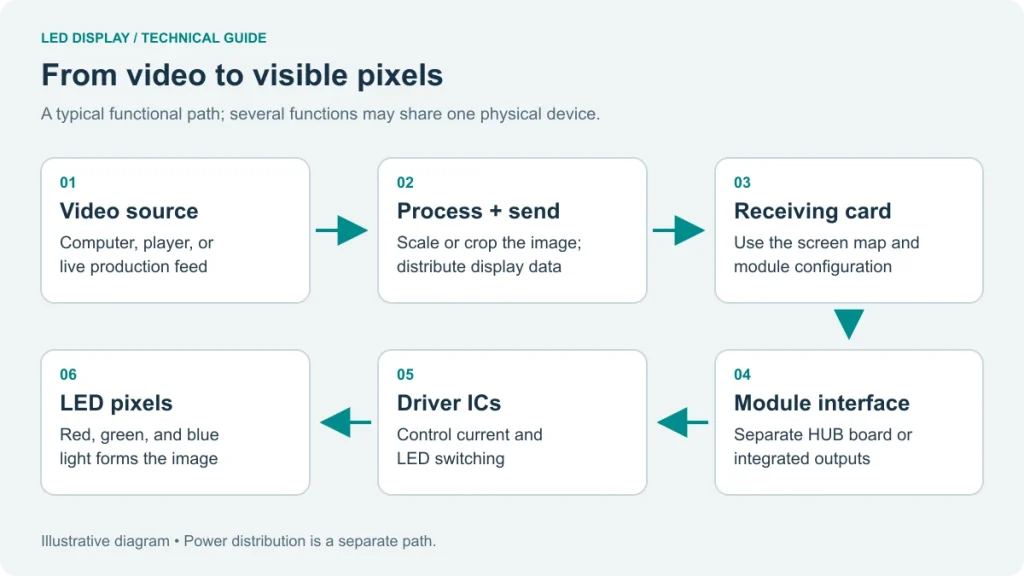 LED Display Signal Flow: Interfaces and Pixel Mapping