
Plan a cylinder LED display by matching whole-module dimensions to the finished circumference, then converting the grid into a pixel canvas. This worked example explains why a nominal 2 m column does not automatically become a 2 m LED surface.
1. Start with the finished display circumference
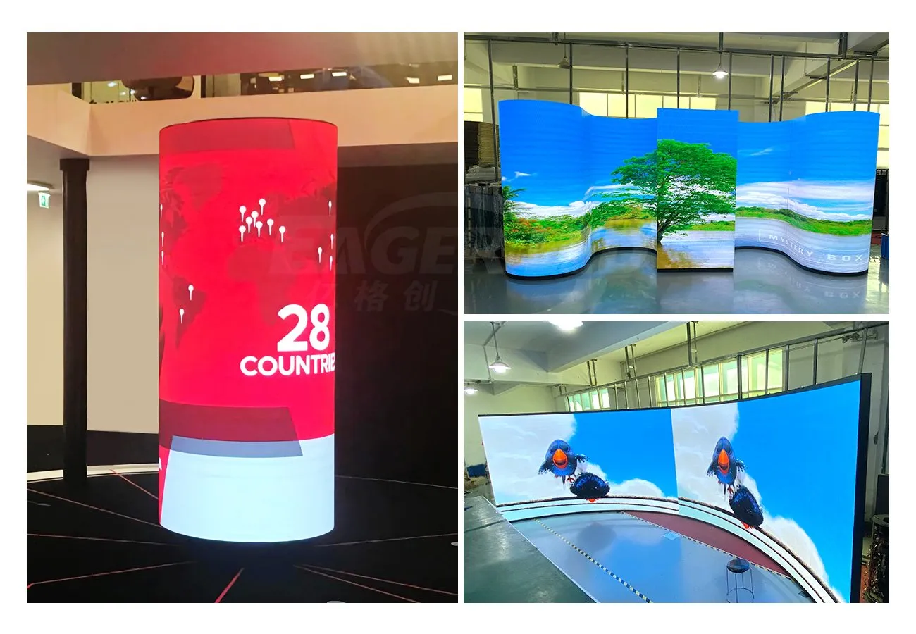
A cylinder LED display wraps a digital image around a curved surface. Before asking for a price, distinguish the existing architectural column from the finished emitting surface: support depth, cabling and the display assembly can increase the outside diameter.
For an ideal circular surface, circumference equals π × diameter. Module widths must then fit the circumference in whole units. Rounding a calculated module count changes the finished size; forcing the last module into a remaining gap is not a design method.
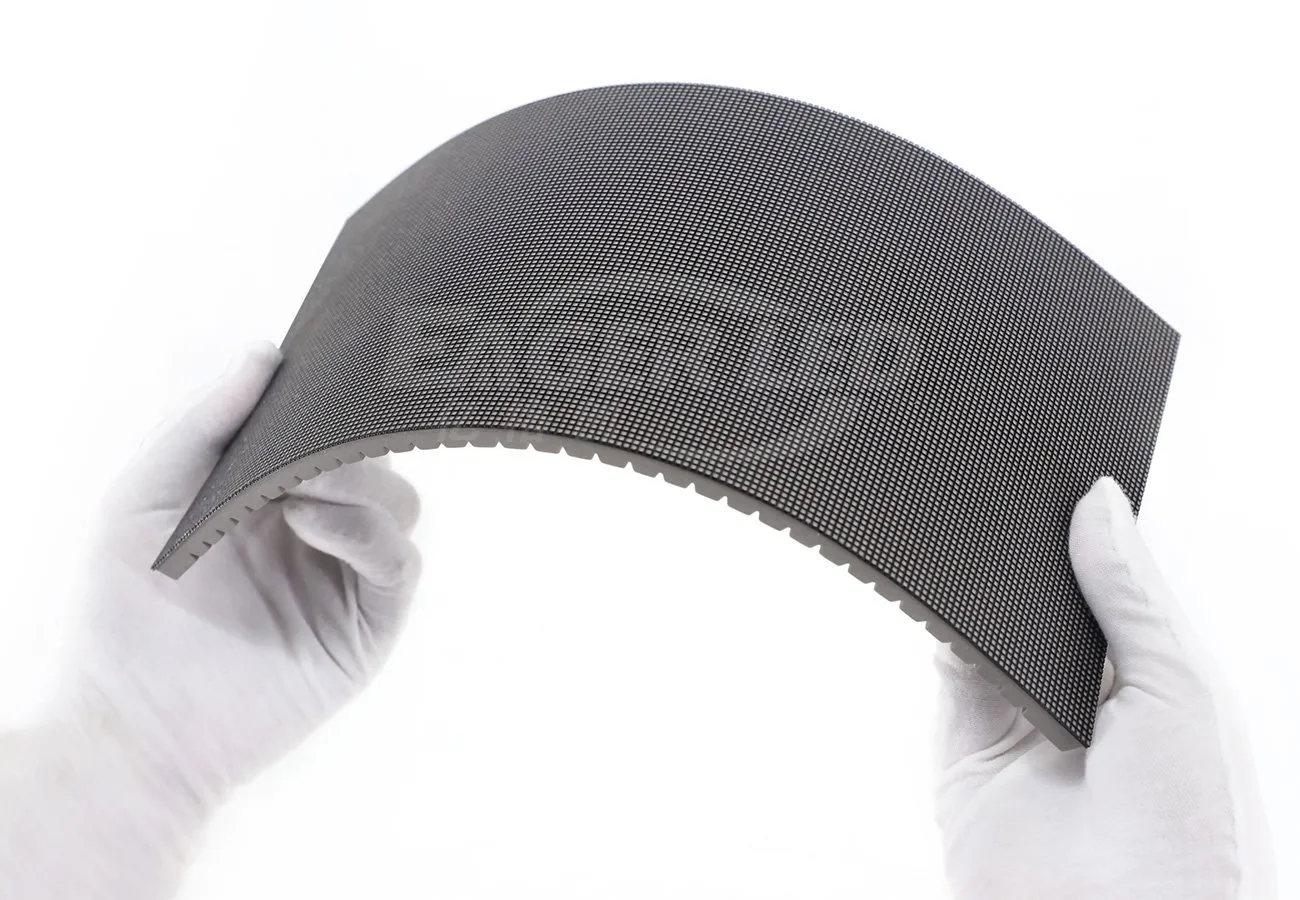
Specify which module edge runs around the cylinder and which runs vertically. A 320 × 160 mm module rotated by 90° produces a different grid. Its allowed bending direction and minimum radius must also be confirmed for the exact model. A flexible module is not permission to bend it arbitrarily.
2. Worked example: 20 modules around, 13 rows high
The EA-Flex product page lists a P2 module option measuring 320 × 160 mm with a 160 × 80 pixel map. The following arithmetic uses that published format. It is an idealized planning example, subject to the supplier approving the selected module, curvature and supporting structure.
| Item | Calculation | Result |
|---|---|---|
| Modules around | 20 × 0.320 m | 6.400 m nominal circumference |
| Equivalent diameter | 6.400 ÷ π | Approximately 2.037 m |
| Display height | 13 × 0.160 m | 2.080 m |
| Module quantity | 20 × 13 | 260 modules |
| Unwrapped pixel width | 20 × 160 pixels | 3,200 pixels |
| Pixel height | 13 × 80 pixels | 1,040 pixels |
This does not specify a 2 m finished cylinder. At an exact 2 m diameter, the ideal circumference would be about 6.283 m; dividing by 0.320 m gives about 19.635 module widths. That fractional result requires a design decision, such as changing the finished diameter or evaluating another approved module format.
The dimensions above use nominal widths and ideal geometry. They exclude frame thickness, installation tolerances, the actual light-emitting surface geometry and any designed seam. Request a dimensioned supplier drawing before treating these numbers as a purchase specification.
3. Translate the module grid into a content canvas
The example gives an unwrapped image canvas of 3,200 × 1,040 pixels, or 3,328,000 pixels. It does not by itself select a controller: the supplier must check total loading, per-port limits, maximum width and height, receiving cards, routing and the intended refresh or color-depth settings.
Provide the content designer with the confirmed cabinet or module map, display orientation, starting point and seam location. A wide flat canvas is useful for file production, but viewers standing beside a cylinder see only part of its circumference at once.
Do not squeeze a normal 16:9 video across the full strip just to fill it. Agree how a logo, short message and background will repeat or move around the surface. Confirm the actual playback method and scaling with the supplied control system.
4. Choose the seam and viewer-facing message zones
Place the wrap seam deliberately relative to entrances, traffic routes and the primary viewing side. Content that crosses the left and right edges of the unwrapped file should join as intended; an otherwise continuous animation may reveal a discontinuity there.
A useful approval file includes numbered grid lines, an orientation arrow, a seam marker, solid colors and representative campaign artwork. Review it from several expected audience positions. Keep important wording within readable viewing zones rather than assuming someone can read around the entire cylinder.
5. Reserve access inside the cylinder
Map the removal route for each component separately: LED module, receiving card, power supply and cable. The product’s magnetic front-service approach supports module removal, but it does not establish that every internal part can pass through the same opening.
Check the space between the original column and finished display, service access points and how technicians reach equipment safely. Ask the supplier to show where cables bend, how assemblies are retained and which parts can be replaced without dismantling the complete cylinder.
The published EA-Flex series is an indoor product with IP31 protection. Do not turn this example into an outdoor specification. Have qualified local professionals assess the support, electrical installation, ventilation and access conditions for the actual site.
6. Approve the drawing and sample before fabrication
Before fabrication, obtain a drawing showing finished outside diameter, emitting height, module orientation, row and column counts, seam position, supports and service openings. Identify the exact module model, pixel pitch and approved bending geometry in the order.
Ask for a representative curved assembly or demonstration where practical. Compare module joints, surface alignment, image mapping and removal access. If a full-size mock-up is unavailable, document which aspects remain unverified and how they will be accepted later.
Keep the approved drawing, pixel map, configuration files and spare-part identifiers together. A change in module size or orientation changes more than the bill of materials: it can affect the structure, pixel canvas and control layout.
7. Frequently asked questions
How many modules fit a 2 m diameter cylinder?
It depends on the module width around the curve and the approved finished geometry. A 2 m ideal circle has about 6.283 m circumference. With 320 mm nominal widths, that is about 19.635 widths, so it does not produce a whole-module ring without a design change.
Is the calculated diameter the architectural column diameter?
No. The example describes an ideal nominal display circumference. The architectural column, support assembly and finished emitting surface require separate dimensions.
Does a 3,200 × 1,040 canvas select the controller?
No. The complete pixel loading and control-system limits must be checked, including output routing and the intended operating settings.
Can every flexible module form this cylinder?
No. Confirm the chosen module’s bending direction, minimum radius, mounting method and operating conditions with the supplier.
8. Request a cylinder LED display layout
Send the existing column dimensions, desired finished diameter and height, indoor environment, nearest viewing distance, country and purchase timeline. Include site drawings, audience approach directions and sample artwork. Request a module grid, approved curvature, control layout and service-access drawing.
Reviewed October 16, 2026. Geometry and pixel totals are illustrative calculations from a published module format; they are not an approved structure, quoted system or tested installation.
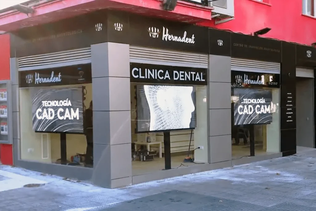 LED Window Display: Test Readability Through Glass