Related Posts
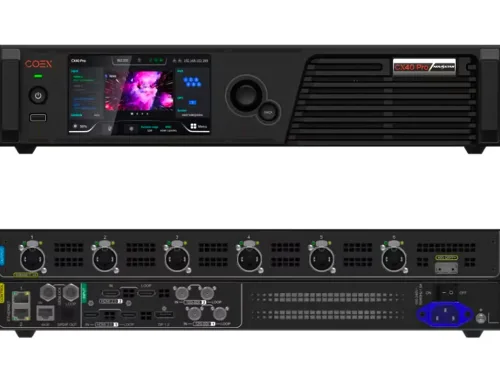


Colorlight VX20 is a 4K-capable video wall processor designed for professional LED display control in live events, staging, and fixed installations. It processes and manages multiple video sources, supports high-resolution output up to 3840×2160, and provides reliable signal handling with built-in redundancy features. This guide covers the VX20’s specifications, setup steps, connectivity options, and configuration tips to help users deploy it effectively.
catalogue
1.What is the Colorlight VX20 Video Wall Processor?
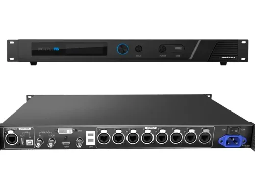
Colorlight VX20 is a professional-grade video wall processor built for real-time control of LED displays in staging, rental, and commercial environments. Unlike basic scalers or switchers, the VX20 processes high-resolution video inputs—up to 4K at 60Hz—and outputs them across multiple LED panels with precise synchronization and minimal latency.

As part of Colorlight’s VX series, it functions primarily as an LED video processor, handling tasks like windowing, layer mixing (Main/PIP1/PIP2), frame rate conversion, and signal redundancy. It supports three operational modes:
- Video processor mode (full processing for LED walls),
- Bypass mode (pixel-perfect pass-through without processing),
- Fiber optic transceiver mode (for long-distance signal extension).
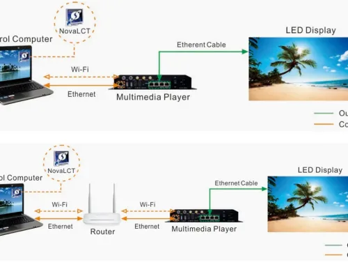
Users manage the VX20 through a web-based interface accessible from any device on the same network—no additional software required. This makes it especially useful for live events where quick setup and remote control are essential.
2.VX20 Video Wall Processor Specifications Analysis
Understanding the technical capabilities of the Colorlight VX20 helps determine if it fits your project’s resolution, input, and reliability requirements. Below is a breakdown of its key specifications based on official documentation:
| Category | Specification |
|---|---|
| Max Input Resolution | 3840×2160 @60Hz (4K UHD) |
| Min Input Resolution | 800×600 @60Hz |
| Custom EDID Support | Yes – up to 4096 pixels wide or tall (e.g., 4096×1080 or 1080×4096 @60Hz) |
| Color Depth | 8-bit |
| Input Refresh Rates | 23.98 Hz to 120 Hz |
| Color Formats | RGB, YCbCr 4:4:4, YCbCr 4:2:2 |
| HDR Support | No |
| Interlaced Signals | Not supported |
| HDCP Compliance | HDCP 1.4 (on HDMI inputs) |
| Audio Input | HDMI 3 only |
What This Means in Practice:
- The VX20 accepts standard 4K signals from cameras, media servers, or laptops via HDMI 2.0 or DisplayPort 1.2.
- It can handle non-standard resolutions often used in creative LED setups (like ultra-wide or portrait-oriented walls) thanks to custom EDID support.
- While it doesn’t support HDR or interlaced video, this is rarely a limitation in professional staging environments where progressive, SDR content dominates.
- Audio is passed through only on HDMI 3—useful for monitoring but not for multi-channel audio routing.

3.Key Features of the Colorlight VX20 Processor
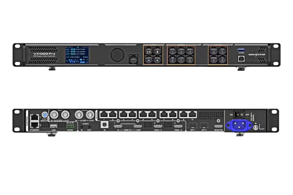
Colorlight VX20 video wall processor delivers field-tested functionality for live events, broadcast, and fixed LED installations. As a full-featured LED video processor, it combines real-time control, redundancy, and web-based management in a single 1U chassis.
Three Operating Modes
- Video Processor Mode: The VX20 processes up to three inputs (Main + PIP1 + PIP2) and outputs to LED receiving cards with just 1-frame latency—ideal for dynamic stage visuals.
- Bypass Mode: Provides zero-latency, pixel-perfect pass-through for critical feeds like camera returns or IMAG.

- Fiber Transceiver Mode: Extends signals over long distances by receiving from another Colorlight LED processor via fiber and retransmitting over Ethernet.

Built-in Redundancy
- Supports dual-unit processor redundancy: Connect two VX20 units (primary + backup) to the same display for automatic failover—no external switcher needed.
- Dual SFP+ fiber ports allow signal duplication or backup paths.
- Dual Gigabit Ethernet ports ensure network continuity during cable faults.
Web-Based Control
Access the full interface from any device on the same network using a browser—no proprietary software. This makes the Colorlight VX20 easy to configure from a laptop backstage or a tablet in the control booth.
Background & OSD Management
- Upload custom background images or set solid colors (with R/G/B input) for clean standby screens.
- Add scrolling text overlays (OSD) with adjustable speed, direction, opacity, and position—useful for lower-thirds or event branding.
HDMI Monitoring Output
The front-panel HDMI OUT shows PVW, PGM, and all input sources simultaneously, giving operators immediate visual feedback without needing a separate multiviewer.
4.How the VX20 Video Wall Processor Enhances Your Video Wall Setup
Colorlight VX20 video wall processor isn’t just about handling signals—it directly improves reliability, flexibility, and operational efficiency in real-world LED deployments. Here’s how it makes a measurable difference on site.
Enables True 4K Input for Large-Scale Walls
Many LED processors downscale 4K sources to HD before output, creating quality loss. The VX20 accepts native 3840×2160@60Hz input and maps it pixel-accurately across your LED array—critical when using high-resolution media servers or broadcast feeds for stage backdrops or corporate events.

Reduces On-Site Complexity
With built-in layering (Main + PIP1 + PIP2), you can overlay graphics, lower-thirds, or backup cameras without adding external switchers or mixers. This simplifies cabling, reduces points of failure, and cuts setup time—especially valuable in fast-turnaround rental scenarios.
Eliminates Single Points of Failure
As an LED video processor, the VX20 includes multiple redundancy layers:
- Dual-unit failover ensures your show continues if one unit fails.
- Fiber 3/4 ports provide backup data paths in fiber transceiver mode.
- Dual LAN ports maintain network control even if one cable is damaged.
- These features are not theoretical—they prevent costly blackouts during live performances or broadcasts.
Speeds Up Troubleshooting and Control
The web UI lets operators adjust scaling, position, or source selection from any device on the network. Need to swap a camera feed mid-event? No need to climb scaffolding—just open a browser on your phone. This remote access capability is especially useful for large or elevated video walls.
Supports Clean Standby and Branding
When no program signal is active, the VX20 video wall processor can display a custom background or solid color—no blank screen or “no signal” message. You can also add scrolling text (e.g., event name, sponsor logo) via OSD, turning idle time into branding opportunity.
Works Seamlessly with Existing Colorlight Ecosystem
If you’re already using Colorlight receiving cards (like the HUB75-based RX series), the VX20 integrates out of the box. It outputs directly over Ethernet using standard protocols—no gateway or converter needed.
5.VX20 Video Wall Processor Installation: Step-by-Step Guide
Installing the Colorlight VX20 video wall processor takes minutes when you follow this practical workflow. No special software is required—just a network cable and a web browser.
What You’ll Need
- Colorlight VX20 unit
- Power supply (included)
- HDMI or DisplayPort source (e.g., media server, laptop, camera)
- Ethernet cables (Cat6 recommended)
- LED receiving cards (e.g., Colorlight RX series)
- Computer or tablet for configuration
Step 1: Mount and Power the Unit
- Install the VX20 in a 19″ rack or place it on a stable surface with ventilation.
- Connect the included power adapter and turn it on. The front-panel LEDs will indicate power and status.
Step 2: Connect Video Input
- Use HDMI or DisplayPort to connect your primary video source to one of the input ports (HDMI 1–3 or DP 1–2).
- For multi-source setups (e.g., Main + PIP), connect additional sources to other inputs.
- Tip: HDMI 3 supports audio pass-through if you need embedded audio monitoring.

Step 3: Link to LED Receiving Cards
- Connect Ethernet Port 1 (or Port 2) to your first LED receiving card using a standard Cat6 cable.
- For redundancy: Connect both Ethernet ports to form a loop between receiving cards (primary and backup paths).
- Note: The VX20 outputs video over Ethernet using Colorlight’s native protocol—compatible with RX series and most HUB75-based receiving cards.
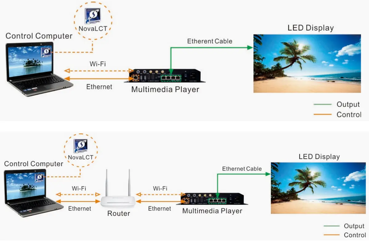
Step 4: Access the Web Interface
- Connect your computer to the same network as the VX20 (via switch or direct cable).
- Open a browser and enter the VX20’s default IP (usually 192.168.1.100—check label or use DHCP discovery).
- Log in (default credentials: admin / admin).
Step 5: Configure Output Layout
- Go to Preconfig > Layout.
- Define your LED wall resolution (e.g., 1920×1080 pixels) and map it to the number of receiving cards.
- Assign which Ethernet port controls which section (if using dual outputs).
Step 6: Select and Preview Sources
In the main interface, click Main, PIP1, or PIP2 to assign input sources.
Use the PVW (Preview) area to position, scale, or crop layers before taking them live.
Step 7: Enable Redundancy (Optional but Recommended)
- For critical shows: Set up a second VX20 as backup.
- In More > Advanced > Processor Redundancy, enable sync mode and link the two units via Ethernet.
- Both units will share configuration; the backup auto-takes over if the primary fails.
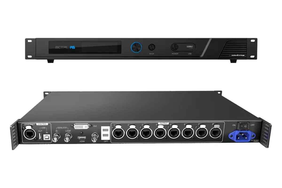
6.Supported Signal Formats and Connectivity Options
Colorlight VX20 video wall processor supports a range of industry-standard inputs and signal types, making it compatible with most media servers, laptops, cameras, and playback devices used in live production. Below is a detailed breakdown of what it accepts—and what it doesn’t—so you can plan your signal chain accurately.
| Port Type | Quantity | Max Resolution & Refresh Rate | Notes |
|---|---|---|---|
| HDMI 2.0 | 3 | 3840×2160 @60Hz | HDCP 1.4 supported; audio embedded on HDMI 3 only |
| DisplayPort 1.2 | 2 | 3840×2160 @60Hz | No audio support |
| 12G-SDI | 2 | 3840×2160 @60Hz (progressive only) | Interlaced signals not supported;10-bit YCbCr 4:2:2 |
| 12G-SDI Loop Out | 2 | Passes through input signal | For daisy-chaining or monitoring |
Supported Signal Characteristics
- Frame Rates: 23.98 Hz, 24, 25, 29.97, 30, 50, 59.94, 60 Hz
- Color Formats:
- HDMI/DP: RGB, YCbCr 4:4:4, YCbCr 4:2:2
- SDI: YCbCr 4:2:2 only
- Color Depth: 8-bit (HDMI/DP), 10-bit (SDI)
- Custom Resolutions: Yes—via EDID customization (up to 4096 pixels wide or tall, e.g., 4096×1080@60Hz)
Genlock & Synchronization
- GENLOCK Input: 1× BNC (Black Burst, Bi-level, Tri-level)
- Supported Frame Rates: 23.98–60 Hz
- GENLOCK LOOP: 1× BNC output to daisy-chain sync to other devices
Output & Control Interfaces
| Interface | Purpose |
|---|---|
| Ethernet (x2, RJ45) | Primary video output to LED receiving cards; also used for web control and redundancy |
| USB Type-B (IN) | Firmware update or PC-based debugging |
| USB Type-A (OUT) | Cascading to another VX unit (rarely used in typical setups) |
| RS232 (RJ11) | Integration with third-party control systems (e.g., Crestron, Q-SYS) |
| HDMI OUT | Local monitoring of PVW/PGM and all inputs |
Not Supported
- HDR (HDR10, HLG, Dolby Vision)
- Interlaced video (e.g., 1080i, 576i)
- Analog video (VGA, component, composite)
- Audio routing beyond HDMI 3 embedding
7.Optimizing Performance: How to Set Up the VX20 for 4K Video Walls
To run a clean, stable 4K LED wall with the Colorlight VX20, follow these key steps:
Use native 4K input: Feed a 3840×2160@60Hz signal via HDMI 2.0 or DP 1.2. Avoid upscaling lower-res sources.
Stay in Video Processor Mode: Required for layering (Main/PIP), scaling, and background control. Bypass mode doesn’t support multi-source 4K processing.
Set correct output resolution: In Preconfig > Layout, match the total pixel count of your physical LED wall (e.g., 3840×2160).
Enable Genlock if syncing multiple sources: Connect house sync to the GENLOCK BNC input to avoid frame drift in broadcast or multi-camera setups.
8.FAQs
9.Conclusion
With native 4K input support, web-based control, and field-tested reliability, the VX20 stands out as a practical choice among video wall processors—especially for professionals who need things to work the first time, every time.