Related Posts


Novastar software SmartLCT is the configuration software used with NovaStar LED control systems. From building the screen layout to sending parameters to hardware, all key configuration steps are completed inside this tool. Accurate setup directly affects screen mapping, image performance, and overall system stability. This guide explains how to use SmartLCT correctly in real LED display projects, focusing on practical operation and reliable configuration results.
1.What Is Novastar SmartLCT and When Should You Use It?
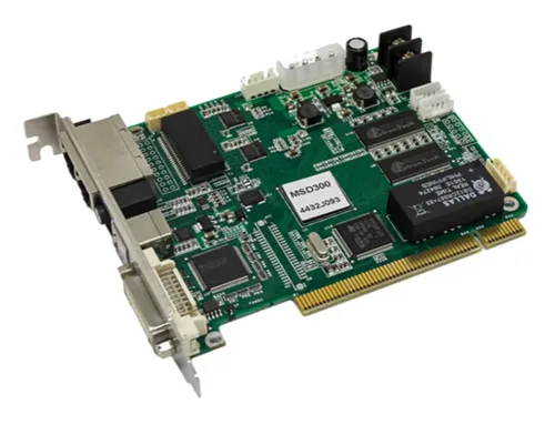
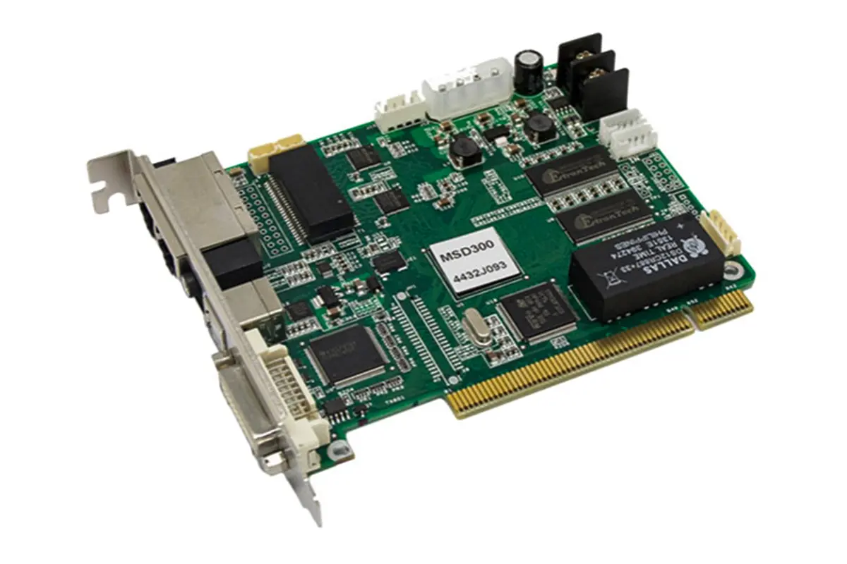
SmartLCT is the official screen configuration software from NovaStar. It works with NovaStar sending devices (including MCTRL300, MCTRL600, MCTRL4K, MCTRL660 PRO, and all‑in‑one controllers like NovaPro HD, VX4S, K16) and receiving cards (such as MRV series, A series, and Armor series) to define how LED cabinets are arranged and how video signals are mapped to the screen.

You need to use Novastar SmartLCT in the following situations:
First time installation
When setting up a new LED screen, you use the software to build the cabinet layout, set connection types (auto or manual), and send the complete configuration to the hardware. It supports both Windows and macOS.
Configuring non‑rectangular screens
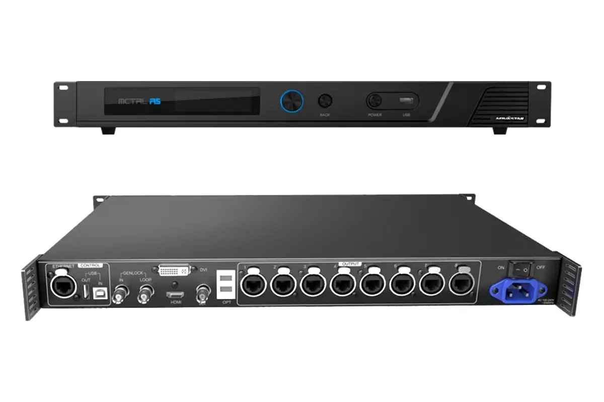
For curved screens, irregular shapes, or rotated installations, LED screen software SmartLCT allows cabinet rotation in 90° increments (with A series receiving cards) or full 360° rotation (with MCTRL R5 controller). You can also group cabinets and set precise offsets.
Adjusting image uniformity
Use seam brightness adjustment to eliminate visible dark lines between cabinets, and batch adjustment to correct brightness and color differences across cabinets of different batches. The LED screen software supports 18‑bit processing and ClearView for improved image quality.
Setting up redundancy
Novastar software SmartLCT provides hot backup configuration – both within a single device (port backup) and between devices – to ensure uninterrupted operation if a connection fails.
Accessing advanced controller features
Through the built‑in V‑Sender module, you can configure advanced functions on compatible controllers: 3D (with MCTRL4K and EMT200 emitter), HDR, picture‑in‑picture, low latency mode, and working as a fiber converter (MCTRL660 PRO).

2.SmartLCT Offline Mode vs Online Mode: How to Choose?
When you open Novastar SmartLCT, the first decision you make is whether to create an offline project or an online project. Here is the difference and how to choose the right one.
Offline Mode
In offline mode, you configure the screen without connecting to actual hardware. You design the cabinet layout, set connections, and create the complete screen configuration on your computer.
Use offline mode when:
- Hardware is not yet installed: You are preparing configuration files before going to site.
- No physical access to the controller: You want to pre-design the screen layout in the office.
- Creating templates: You need to save cabinet configurations for future use.
- Learning the software: You want to understand how Novastar smartlct works without affecting a live display.
In offline mode, you work with virtual devices and cabinets. Once the design is complete, you save the project file and later send it to hardware when connected.

Online Mode
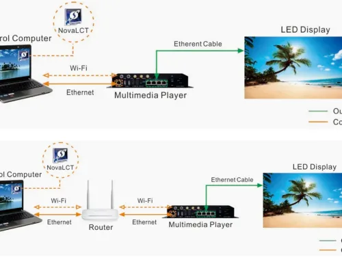
In online mode, LED screen software SmartLCT connects directly to NovaStar controllers on the same network. The software reads back actual hardware information and allows real‑time configuration.
Use online mode when:
- Hardware is connected and powered on: You are on site and ready to configure.
- Reading back existing settings: You need to check or modify the current configuration on the controller.
- Making live adjustments: You want to adjust brightness, test patterns, or perform seam brightness adjustment while seeing results on the screen.
- Updating firmware: You need to upgrade receiving card or controller programs.
- Performing maintenance: You are replacing a faulty cabinet and need to copy parameters from a reference cabinet.
3.How to Create a New Screen Project in Novastar SmartLCT
Creating a new project in Novastar SmartLCT is the first step in configuring any LED screen. The process differs slightly depending on whether you are working offline or online.
Creating a New Offline Project
Launch SmartLCT. On the start page, click Create Offline Design.
In the dialog box that appears, configure the following:
- Project Name: Enter a name and choose a save location.
- Device: Select your video controller from the list (e.g., MCTRL660 PRO, NovaPro HD, VX4S).
- Cabinet Selection: Choose the manufacturer and cabinet model you are using. If your cabinet is not listed, you can add it later through Cabinet Management.
- Cabinet Columns/Rows: Enter the number of cabinets horizontally and vertically.
- Connection Type: Select Auto Connect to let the software automatically link cabinets based on loading capacity, or leave it unchecked for manual connection.
- Source Resolution: Set the maximum input resolution of the selected device – this defines the total width and height the controller can handle.
- Click OK. The LED screen software creates a blank canvas with virtual cabinets placed according to your settings. You are now in the Edit page and can begin detailed configuration.

Creating a New Online Project
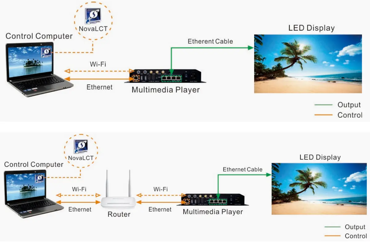
Launch SmartLCT. Ensure your computer is connected to the NovaStar controller via Ethernet.
On the start page, click the refresh icon next to Device List to scan for connected devices. The detected controller(s) will appear in the list.
Click Create Online Design.
In the new project dialog, set the same parameters as offline mode:
- Project Name and save path
- Cabinet Selection (manufacturer and model)
- Cabinet Columns/Rows
- Connection Type (Auto Connect or manual)
- Note: Device selection is automatic in online mode – SmartLCT uses the connected hardware.
Click OK. The software reads basic information from the connected controller and opens the Edit page with real hardware as the target.

Key Options at Project Creation
Cabinet Management: Click this button to add, edit, or import cabinet configuration files (*.rcfgx) before you start. This is useful if your exact cabinet model is not in the default list.
Smart Mode: Controls how cabinets are initially placed on the canvas. The default setting works for most standard installations.
Auto Connect: When enabled, SmartLCT automatically links cabinets in the order you specify and prevents connections that exceed an Ethernet port’s loading capacity (progress bar turns red as warning). When disabled, you connect cabinets manually, which allows custom routing but requires attention to loading limits.
4.Adding Cabinets and Configuring Screen Layout
Once your project is created, the canvas is where you build the screen. Here is how to add cabinets and set up the layout.
Adding Cabinets
Go to the Edit tab. You have two ways to add cabinets to the canvas:
- Batch Add: Click Batch Add in the toolbar. Set how many cabinets you need (rows and columns), then click on the canvas to place them all at once.
- Single Add: Click a cabinet icon from the library, then click on the canvas to place them one by one. Right-click to stop.
Each cabinet appears as a rectangle showing its receiving card number. Before adding, select the target device and Ethernet port from the Device section at bottom left – the progress bar shows how many cabinets that port can handle.
If your cabinet model is not in the library, go to Cabinet Management to add it manually or import a cabinet file (*.rcfgx).

Configuring Screen Layout
Once cabinets are on the canvas, you need to define how they connect and where they sit.
Connect Cabinets
- Connections define the signal path from the controller through the cabinets.
- Auto Connect: Enable this in the Properties panel. Novastar software SmartLCT automatically links cabinets in sequence and prevents connections that exceed port capacity (progress bar turns red as warning). This is the fastest method for standard screens.
- Manual Connect: Select cabinets, choose a connection pattern (like S-shape) from the toolbar, then click the first cabinet and drag to the next. You can also click center-to-center.
- Disconnect: Select cabinets and click Disconnect or right-click > Delete Connection.
Adjust Positions
After connecting, a dotted rectangle appears – this is the total loading area. Click and drag any cabinet to adjust its physical position inside this area. Offset values (X, Y) show in the Properties panel.
Rotate If Needed
- 90° increments (A series cards): select a cabinet and choose 0°, 90°, 180°, or 270° from the rotation dropdown.
- Full 360° (MCTRL R5 only): select a cabinet and drag the rotation handle, or set exact values in Properties.
Check Loading
Progress bars at bottom show port usage:
- Blue: within limit
- Red: overloaded (auto connect prevents this)
- Gray: no cabinets assigned
Once the layout matches your physical screen, you’re ready to send configuration to hardware.
5.Novastar SmartLCT Screen Rotation and Irregular Layout Setup
Standard rectangular screens are straightforward, but many LED installations today require creative shapes – curved displays, rotated panels, or irregular layouts. Novastar SmartLCT handles these configurations through its rotation and positioning tools.
Rotation in 90° Increments
For most creative layouts, rotating cabinets in 90° steps is sufficient. This works with A series receiving cards (A4, A4s, A5, A5s, A7, A7s, A8, A8s, A9s, A10s, B4s).
To rotate: select a cabinet, go to Properties panel, and choose 0°, 90°, 180°, or 270° from the rotation dropdown. Multiple cabinets can be rotated individually or as a group.

Full 360° Rotation
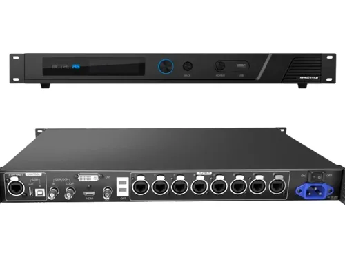
When using the MCTRL R5 controller, Novastar smartlct supports free rotation at any angle.
To rotate: select a cabinet and drag the rotation handle that appears. For precise control, set exact rotation center and angle values in the Properties panel. Grouped cabinets can be rotated together.

Irregular Layouts
Beyond rotation, Novastar software handles non-rectangular screen designs:
- Cabinet Offset: Click and drag any cabinet to adjust its position inside the loading area. This matches physical installations where cabinets are staggered.
- Grouping: Select multiple cabinets and group them to move, rotate, or copy as one unit – useful for repeated patterns.
These tools in LED screen software let you build everything from simple walls to complex creative displays. The canvas shows exactly how the final screen will look before you send configuration to hardware.
6.Image Adjustment: Brightness, Gamma, Color Temperature
Once your screen layout is configured, the next step is getting the image to look right. Novastar SmartLCT provides several tools to adjust brightness, color, and uniformity across the entire display. Here is how to use them.
Brightness Adjustment
- Go to the Color panel on the right side of the screen.
- Locate the Brightness section.
- Drag the slider left to lower brightness, right to increase it. Or click the number field and type a value directly.
- Changes appear on the LED screen immediately when working online.
Gamma Adjustment
- In the same Color panel, find Gamma.
- Drag the slider:Move right (higher value) to darken midtones.Move left (lower value) to brighten midtones.
- Watch the screen to find the right balance for your content.
Color Temperature Adjustment
- In the Color panel, go to Color Temperature.
- Choose a preset: Warm, Cool, or Native.
- For custom adjustment, select Custom and adjust the Red, Green, and Blue sliders individually until white looks correct.

Seam Brightness Adjustment
This fixes visible dark or bright lines between cabinets.
- Click Seam Brightness in the Device tab at the top.
- On the preview window, click the seam between two cabinets. Selected seams turn blue.
- On the right panel, drag the Selected Area Parameter Adjustment slider.
- Adjust until the seam blends with surrounding cabinets (border turns green when adjusted).
- Click Save to HW at the bottom to save to hardware.

Batch Adjustment
Use when cabinets from different batches show color or brightness differences.
- Click Batch Adjustment in the Device tab.
- In the editing area, double-click a cabinet to see individual modules.
- Select a batch from the bottom panel (default has Batch 1 and Batch 2).
- Click modules or cabinets that represent this batch, then click Add to Sample Area.
- Adjust Brightness and Chroma sliders.
- Click Apply Adjustment, then Save to HW.
Additional Options
In the Color panel, you can also enable:
- 18-bit Mode: Check the box for smoother gradients.
- ClearView: Check the box for sharper image clarity.
These LED screen software tools let you dial in the exact look you need. All adjustments are saved to hardware when you click Save or Save to HW.
7.Hot Backup, Sending Configuration and Saving to Hardware
Once your screen layout is configured and image adjustments are done, the final step is sending everything to hardware. Novastar SmartLCT also includes hot backup features to prevent signal loss if a connection fails.
Hot Backup
Hot backup creates redundancy so the screen stays on if a cable fails or a port goes down. There are two types.
Backup Within a Device (Port Backup)
- This backs up one Ethernet port to another on the same controller.
- On the Edit tab, click Hot Backup.
- Drag a device from the left panel onto the canvas.
- Click the backup icon (top right of the device). Ethernet ports pair up automatically – Port 1 backs up Port 2, Port 3 backs up Port 4.
- To change pairing, click a backup port and drag it to a different port.
- Click Apply to send to hardware.
Backup Between Devices
This backs up one entire controller to another. Both devices must have the same communication ports.
- On the Hot Backup page, drag the first device onto the canvas.
- Drag a second device onto the canvas and drop it near the first. They pair automatically – a dashed line appears between them with a switch icon.
- To pair specific ports, click a port on the master device and drag to a port on the backup device.
- Click Apply to send to hardware.

Switching Master and Slave
- Before backup: use the toggle on each device to set which is master and which is backup.
- After backup: click the switch icon on the line between devices to manually switch roles.

Sending Configuration Information
Once layout and connections are set, send the configuration to hardware.
From Offline Mode:
- On the Edit tab, click Send.
- A prompt appears – click Yes.
- In the Match Device dialog, select the connected online device.
- Click OK. Configuration sends to the selected hardware.
From Online Mode:
- On the Edit tab, click Send.
- The configuration sends directly to the connected device – no matching needed.
Saving to Hardware
Different functions save to hardware in different ways:
- Main Configuration: Clicking Send saves the screen layout and cabinet connections to receiving cards.
- Seam Brightness: After adjustments, click Save to HW on the Seam Brightness page.
- Batch Adjustment: After adjustments, click Save to HW on the Batch Adjustment page.
- Color Settings: In online mode, adjustments apply immediately. To make them permanent, go to V-Sender > Properties > Apply.
- V-Sender Settings: Any changes in V-Sender (3D, HDR, PIP, etc.) must be saved by clicking Apply or Save in the V-Sender interface.
8.Using V-Sender in Novastar SmartLCT for Advanced Device Control
V-Sender is the built-in module in Novastar SmartLCT that controls advanced features on NovaStar controllers. While the main Edit page handles screen layout and cabinet configuration, V-Sender manages the controller itself – input sources, output settings, 3D, HDR, and more.
How to Access V-Sender
Open V-Sender from the start page (click the V-Sender icon next to any connected device) or from the Edit page (click the V-Sender icon in the Device section at bottom left).
What You Can Do in V-Sender
Control Input and Display
In the Control tab, select which input source (HDMI, DVI, DP) is active and choose screen display mode – full screen, native resolution, or point-to-point mapping.
Configure 3D, HDR, and Advanced Modes
The System tab contains the most powerful features:
- 3D Function (MCTRL4K only): Enable 3D, set video source format (side-by-side, top-bottom, frame sequential), choose eye priority to match your 3D glasses, and adjust signal delay for sync.
- HDR (MCTRL4K only): Enable HDR and select standard – HDR10 or HLG.
- Low Latency (MCTRL4K and MCTRL660 PRO only): Reduce signal delay from input to output.
- Working Mode (MCTRL660 PRO only): Switch between normal sending card mode and fiber converter mode.


Adjust Input, Output, and Color
The Properties tab gives you precise control over signal processing:
- Input: Set active source, data bits (8-bit or 10-bit), and resolution.
- Color: Adjust contrast, saturation, hue, and sharpness.
- Output: Configure main screen zoom (disable zoom, customize zoom, or auto fit). For screens exceeding one device’s capacity, enable Mosaic and set equal or non-equal division across multiple controllers.
Set Up Picture-in-Picture
If your controller supports PIP, select the PIP tab on canvas, choose a layout (horizontal split, vertical split, or small window in corner), drag to resize screens, and set capture/output parameters in Properties.
Save Configurations as Templates
On supported controllers (V800, V900, VX series, K series), use the Template tab to save current settings to slots 1-10 and load them later.
Monitor System Status
The Information tab shows real-time Ethernet port connections, temperature alarms, and voltage alarms. Icons indicate port status: green for connected primary, yellow for backup connected but inactive, blue for backup active, gray for backup not connected.
V-Sender is where Novastar smartlct becomes more than just configuration software. It gives you full control over NovaStar hardware capabilities.
9.FAQs
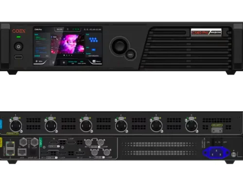
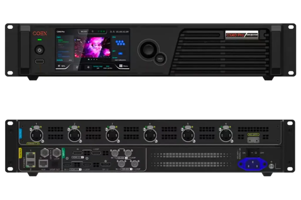 NovaStar LED Controller CX40 Pro Review: 4K HDR Processing,Ultra-Low Latency