
LED light sensor placement affects whether automatic dimming responds to the conditions around a screen or to an unrepresentative patch of light. Position the sensor where it can sample the intended ambient conditions, with access for inspection and the protection required for its environment. Keep it away from direct screen spill, avoid predictable shadows where practicable, and verify the actual brightness response after installation.
For a contractor preparing an outdoor advertising screen, selecting the mounting point is only part of the decision. The sensor, control hardware, dimming rules, and screen output need to work together. Agree on the daytime and nighttime behavior with the client, then use the installed system to check whether the proposed location supports it.
1. What the Sensor Actually Controls
An ambient light sensor measures light at its own location. The control system uses that information according to its configured rules to request a screen brightness level. That reading does not directly measure the display’s emitted luminance or establish how bright the image appears to a viewer at another position. Those are separate observations to include in commissioning.
For example, a sensor located under an overhang may remain shaded while the screen face and surrounding area are in daylight. Another mounted beside a floodlight may report bright conditions after the audience area has become dark. Both sensors could be functioning correctly while reporting conditions that are poorly matched to the intended dimming policy.
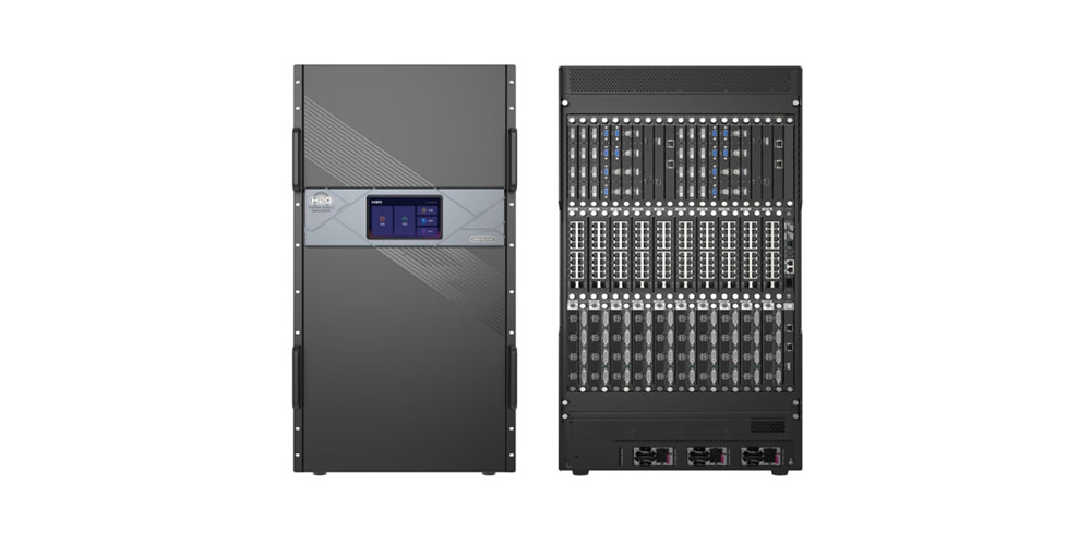
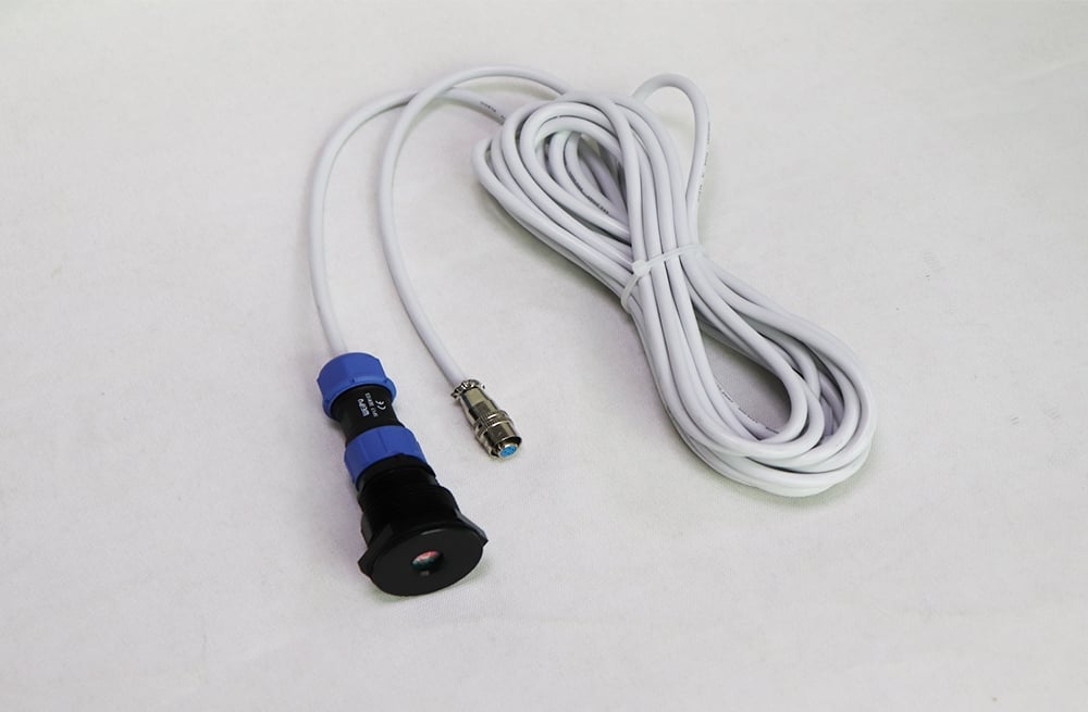
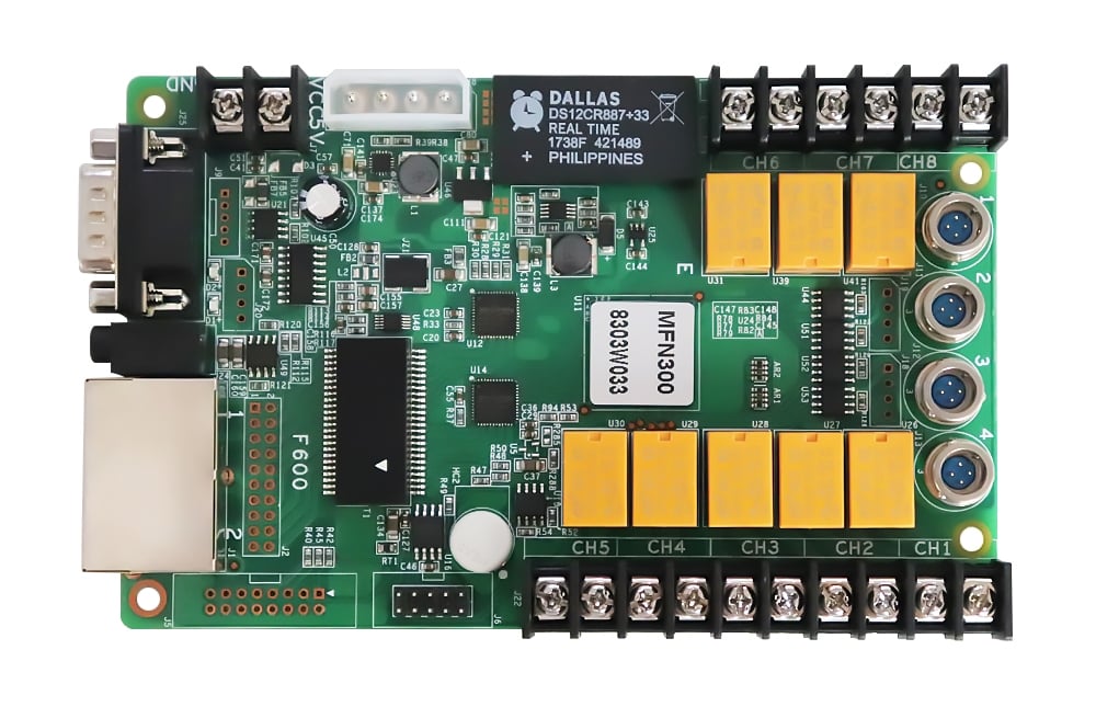
Check how the sensor connects to the proposed system. Some controllers provide a dedicated light-sensor connector, while other installations use a supported multifunction card. NovaStar documentation describes both arrangements for relevant systems. Confirm the supported sensor model, connector, cable arrangement, and software functions before the mounting detail is approved. Our light sensor compatibility guide covers that parts check.
LED light sensor placement should therefore be reviewed alongside the control drawing. Include the route from the sensor to the controller or peripheral card, the location of any intermediate equipment, and the access required to inspect it. Ask the supplier to confirm the applicable environmental limits and installation instructions for the actual sensor.
2. Choose LED Light Sensor Placement for the Site
Start with a site walk at representative times. Identify the screen orientation, the surrounding lighting, and objects likely to shade a candidate position. An adjacent roof, a sign support, or nearby trees can change the light falling on a sensor without producing the same change across the viewing area. Record these conditions on the proposed mounting drawing.
The most convenient cable exit is not necessarily the best sampling position. A rear-mounted sensor may experience different light from the front of a freestanding screen. A sensor facing a reflective wall may respond to a nearby surface more than to the broader environment. Ask which conditions the automatic adjustment is intended to follow before choosing between mounting locations.
Keep direct light from the display out of the sensor’s field where the installation allows it. Otherwise, changes in screen content or brightness can influence the reading used to control the screen. Review the sensor’s orientation and any surrounding reflections with the supplier. A mounting point that works during a dark test image may behave differently during a bright advertisement.
Good LED light sensor placement also allows inspection. A reading that becomes unreliable after dirt accumulates or a new obstruction appears needs investigation at the sensor. Use an accessible, approved mounting arrangement rather than assuming every future check can be performed through software. Follow the site access procedure and the manufacturer’s cleaning instructions.
| サイト観察 | 考えられる影響 | 記録するもの |
|---|---|---|
| A roof shades the sensor while the screen surroundings remain bright | The control system may select a dimmer level than intended | Time, shadow boundary, candidate mounting point, and screen appearance |
| A nearby fixture illuminates the sensor after dark | The reading may stay high during the nighttime operating period | Fixture schedule, direction, and readings with it on and off |
| The sensor faces the screen or a strong reflection of it | Content changes may affect the measured environment | Test image, brightness setting, sensor orientation, and observed response |
| The mounting point will become difficult to reach | Cleaning and fault inspection may be delayed | Approved access method and maintenance responsibility |
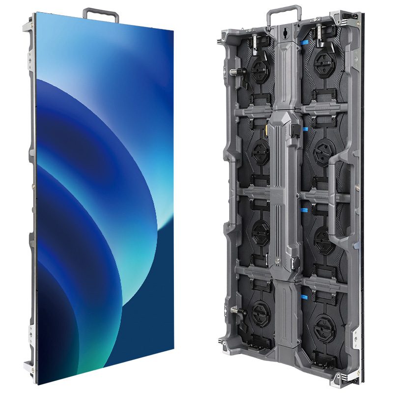
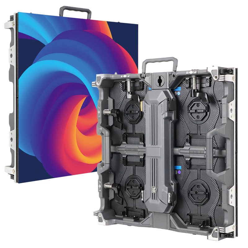
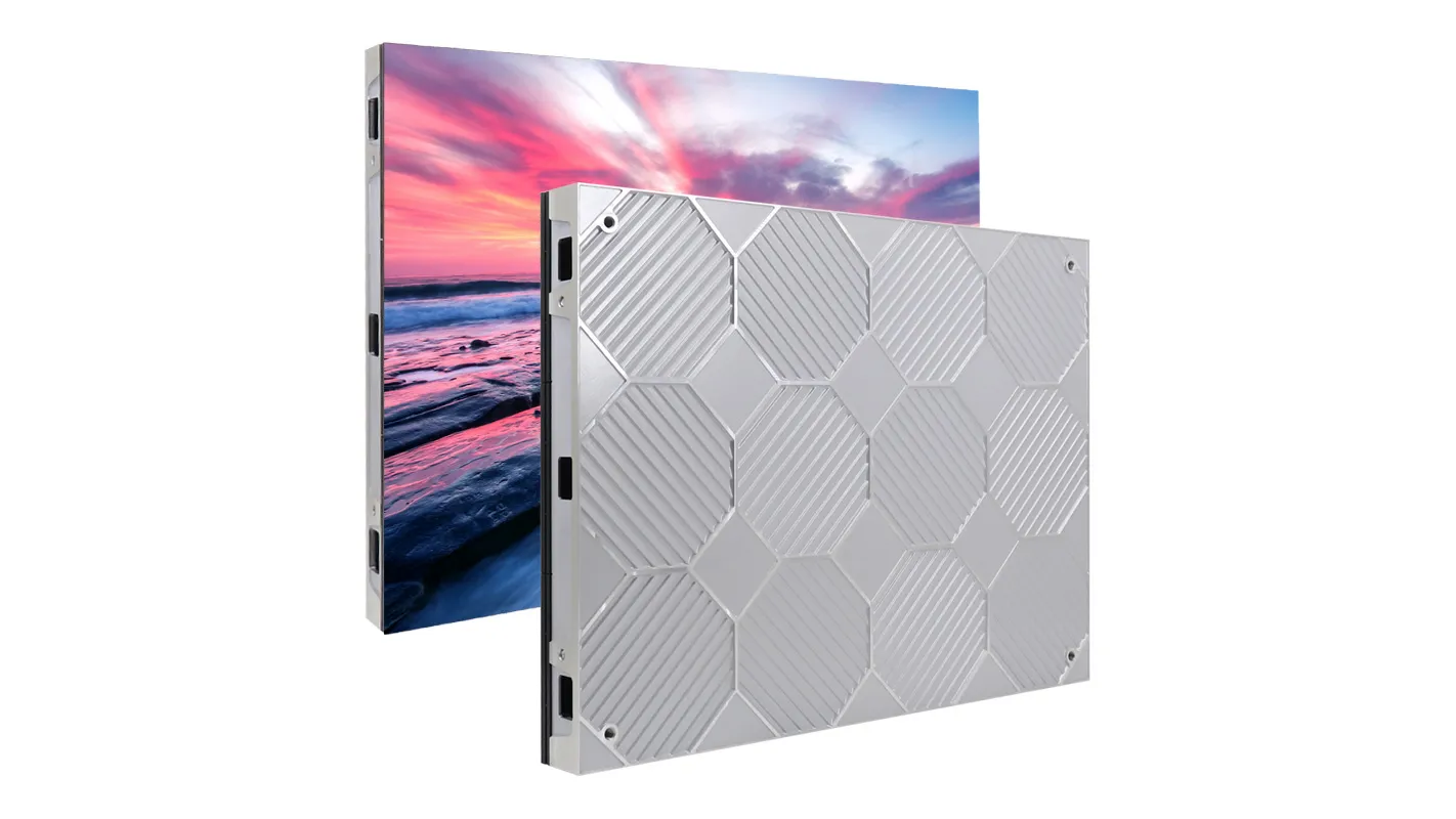
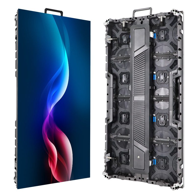
その EA1000F2 outdoor display page illustrates varied surroundings. These product illustrations do not establish sensor locations or measured dimming results.

3. Separate Sensor Readings from Dimming Rules
Even suitable LED light sensor placement cannot compensate for an unsuitable mapping between ambient conditions and screen output. Review the brightness rules separately from the physical mounting. The project needs an approved range of operating levels and a clear description of when schedules, manual commands, or automatic adjustment take priority.
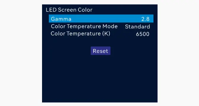
In NovaLCT V5.4.4.5, the manual distinguishes software and hardware automatic adjustment modes. Its software mode depends on the control PC being connected and monitoring running, while its hardware mode lets supported sending hardware adjust brightness without that monitoring connection. Check the corresponding behavior on the installed system. Do not assume the same dependence or limitations apply to every controller and software release.
Agree on what happens when the input reading is unavailable or unreliable. The actual product documentation should establish its fault behavior and supported options. Record the operator’s approved response, the normal brightness preset, and the person responsible for investigating the fault. Avoid leaving a manual override active without a record of why it was applied.
Compare percentage settings carefully. A percentage in a control interface is not itself a measured luminance value or a universal standard for nearby residents, drivers, or customers. Confirm the applicable project requirements with the responsible team and approve the screen’s appearance under the real conditions. Retain measurements where the acceptance plan requires them.
4. Verify the Installed Response
Test LED light sensor placement with the normal control configuration and representative content. Record the sensor reading if the system exposes it, the requested brightness level, the active mode, and the visible result. Change one variable at a time so the commissioning team can distinguish a mounting problem from a rule or connection problem.
Observe the system during the transition between daytime and evening conditions where practical. A test performed at noon cannot establish how a nearby building light affects the sensor after sunset. If commissioning cannot cover all required conditions, identify the outstanding observation and assign a follow-up time instead of treating the missing evidence as complete.
Compare a bright image with a darker image while the surrounding lighting remains as stable as possible. If the reported ambient reading follows the displayed content, investigate spill or reflections at the sensor. Also check the software configuration before moving hardware. A symptom alone does not establish which part of the system needs correction.
After changing LED light sensor placement, repeat the relevant observations and update the drawing. Keep the original and revised locations in the change record. If the sensor stays in place but the mounting structure, decorative lighting, or nearby sign changes, reassess whether the original sampling conditions still apply.
Include the normal operator workflow in the test. Confirm how an authorized operator recognizes automatic mode, applies a permitted override, and restores the approved behavior. Where supported, verify the configuration after the agreed restart procedure. A setting visible in a connected laptop session should be checked in the operating state the client will actually use.
Consider a proposed installation beside a shopping center entrance. The daytime demonstration takes place with the canopy in shade and the parking area in direct sun. After dark, the entrance lights operate on a separate schedule. Before accepting the location, ask the contractor to observe both states and compare what the sensor sees with the conditions the screen is meant to serve. This is a planning example, not a measured EagerLED インストール。
Make the acceptance record specific enough for another technician to repeat. A note that says “automatic brightness works” omits the time, lighting state, active rules, and viewing position. A short set of paired observations provides a better starting point when the client reports a later change in behavior.
5 よくある質問
Can two nearby screens use the same sensor?
Only where the selected control system supports that arrangement and the project accepts the shared reference. Different screen orientations or surrounding lights may justify separate measurements. Confirm which screens receive the command and test the result at each one.
Should a sensor be hidden inside the cabinet?
Use the manufacturer’s specified sensing arrangement. A sensor enclosed behind an opaque panel cannot sample the outside environment as intended. Confirm the sensor window, enclosure protection, and approved mounting detail with the supplier.
Does automatic dimming prove that nighttime brightness is acceptable?
No. Automatic adjustment only follows the supported configuration and measured input. The project still needs an agreed acceptance check under nighttime conditions and any applicable requirements identified by the responsible team.
What should be checked after replacing the sensor?
Confirm the replacement is supported, check its orientation and connection, and review the active rules. Repeat the relevant site observations before closing the service record. A matching housing does not prove identical configuration requirements.
6. Record the Approved Location and Operating Rules
Approve LED light sensor placement together with the sensor model, control path, dimming rules, access arrangement, and test observations. Keep the approved mounting photograph and the normal operating preset in the handover pack. For a project review, contact EagerLED ディスプレイ要件について with the screen location, orientation, controller model, surrounding lighting, and expected operating hours.
 LEDキャビネットのラベル表示:資産ID、位置、データ順序