
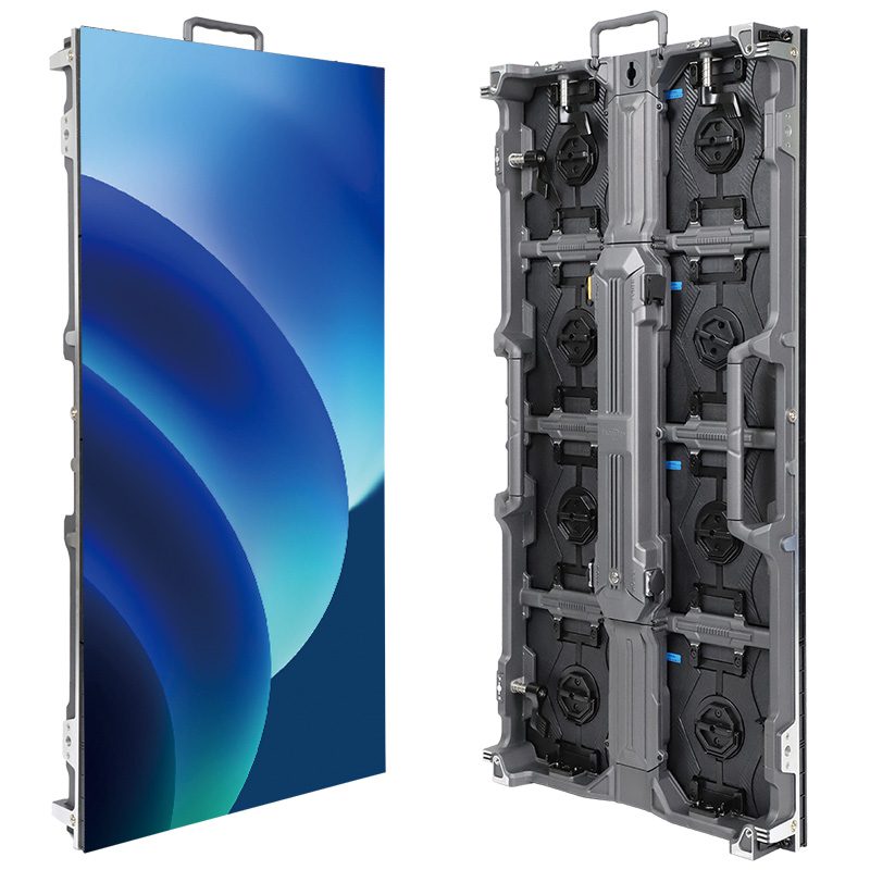
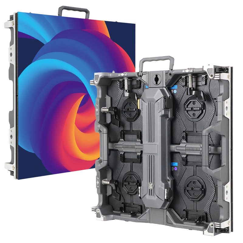
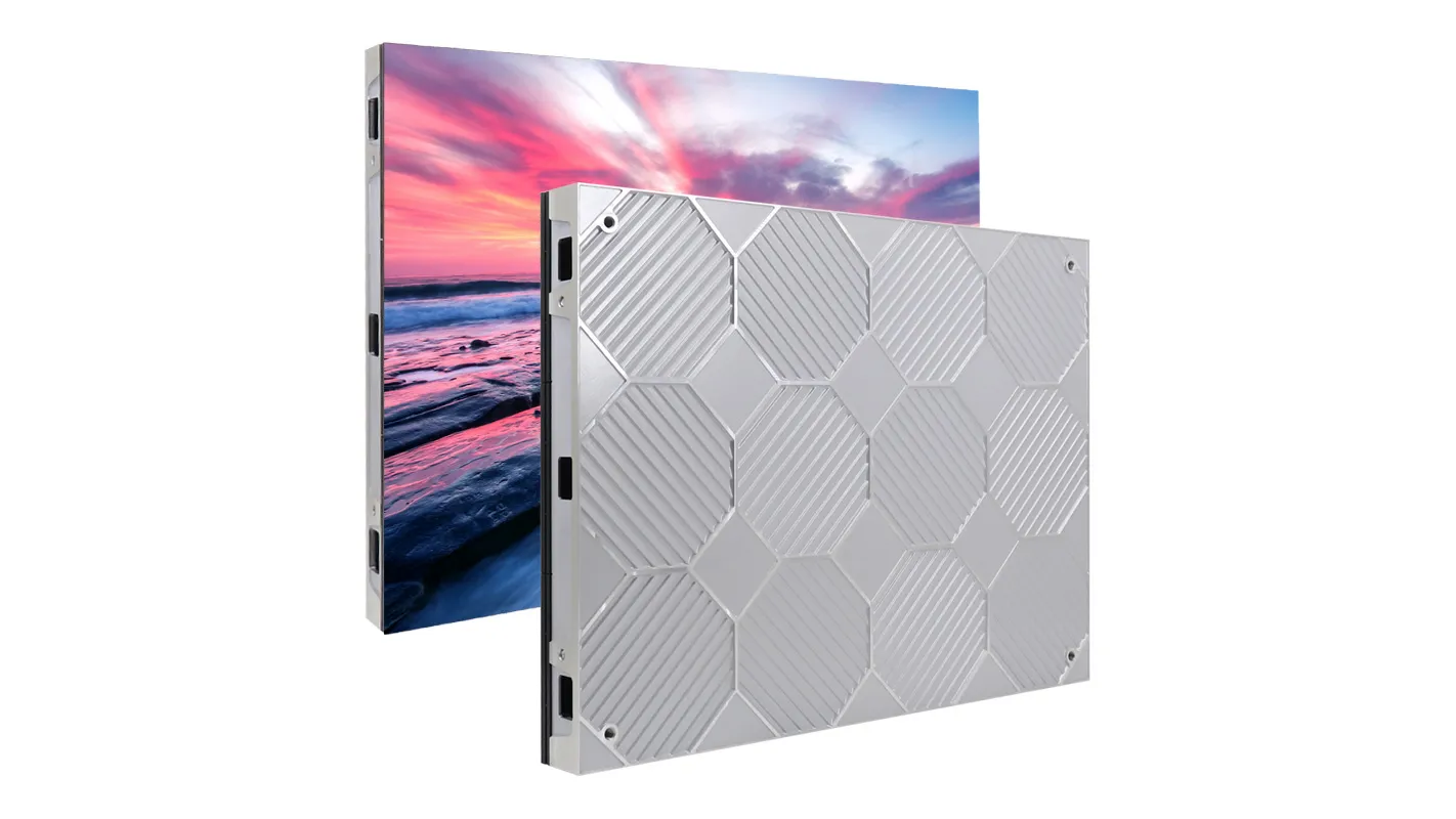
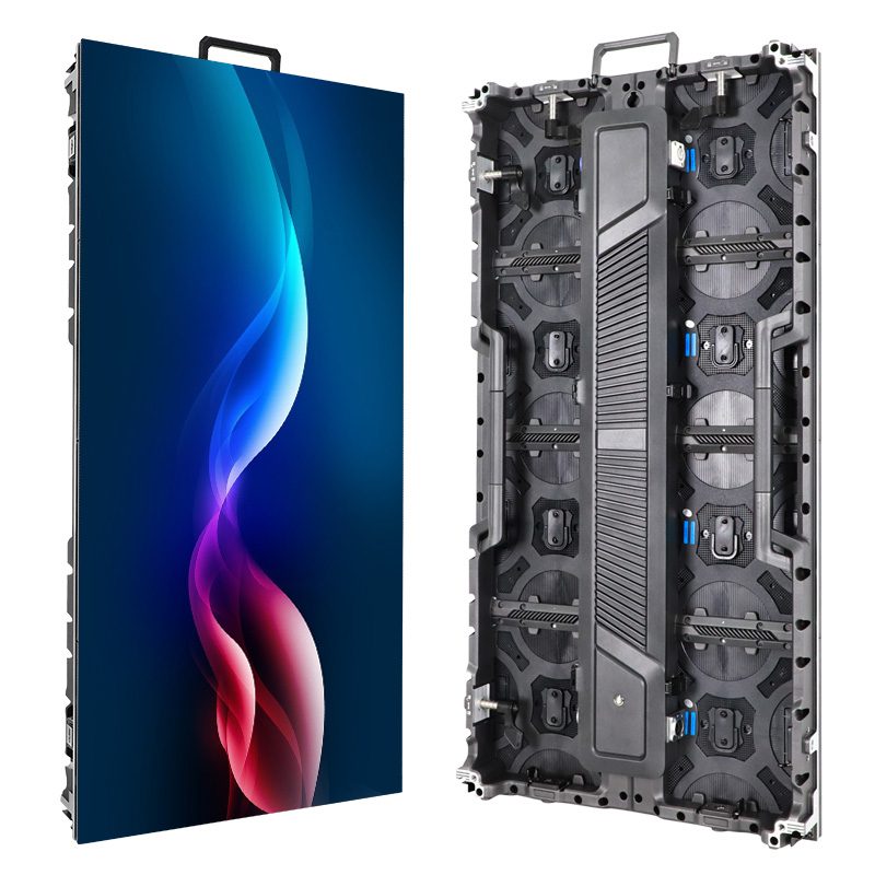
An LED wall test pattern is a known image used to check how a modular display handles color, geometry, or pixel mapping. Choose the image to match the symptom. Solid red, green, and blue fields help reveal missing color channels. A numbered grid shows whether cabinets display the right part of the image. A gray ramp makes abrupt tone changes easier to see.
For an AV integrator evaluating a demonstration wall before specifying an indoor display, the same image can answer two different questions. A pattern generated by the controller checks the portion of the system downstream of that generator. A matching pattern sent through the intended player checks more of the route the installation will actually use.
1. Where an LED Wall Test Pattern Starts
Ask the supplier where the built-in generator sits and which stages it bypasses. On some setups, a sending controller produces the pattern and distributes it to the receiving cards. A receiving-card test, when available, starts farther downstream. The test can only provide evidence about the part of the system that carries or displays it. The device manual and the proposed configuration establish that boundary.
For the second pass, play a known test file through the intended media player or laptop, using the proposed switcher and processor input. That path adds variables such as source timing, scaling, range settings, and input routing. Label the two runs in your notes. If the supplier can only show the built-in pattern remotely, arrange a separate check of the intended source before you approve the complete system.
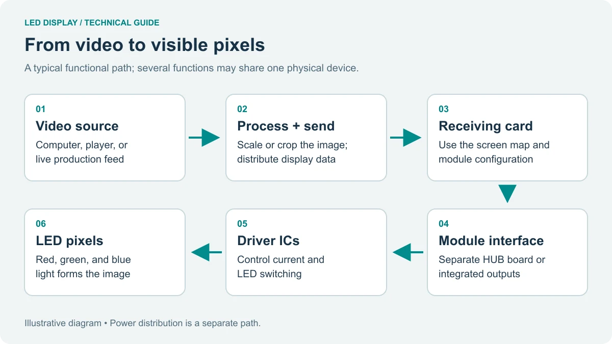
Compare the results at the same wall brightness preset and with the same screen configuration. Record both the controller preset and the source format. If you change the brightness and the input at the same time, you may have to repeat the demonstration to find out which change affected the picture. The signal-flow and pixel-mapping guide explains which functions can share the same piece of hardware.
2. Choose an LED Wall Test Pattern for the Symptom
Choose the simplest LED wall test pattern that makes the fault visible. For example, a red logo may look patchy across the middle of a wall. Hold a solid red field and note where the defect begins and ends. Then run green and blue separately. Record whether the mark affects a single pixel, a line, a module, or a whole cabinet. The footprint gives the supplier a location to investigate before anyone adjusts calibration or replaces hardware.
| Sintomo visibile | Pattern to run | Prove per catturare |
|---|---|---|
| One point looks bright on dark content | Black field, followed by the three primary colors | Record which fields reproduce the point and whether nearby pixels behave the same way. |
| Small text looks soft everywhere | Native-size one-pixel bars, then the actual text asset | Check whether the bars remain distinct along both axes. Record the source and processor sizes if they merge. |
| A straight edge jumps at one cabinet | Crosshatch with cabinet labels and a perimeter border | Note whether the label is in the wrong position or the line shifts while the label remains correct. |
| A shadow breaks into steps | Grayscale steps and a smooth near-black ramp | Record the first step you can distinguish at the expected room lighting and operating preset. |
| Scrolling graphics break across part of the wall | Moving line across the affected region | Log direction, input frame rate, and the location of the break so the same run can be repeated. |
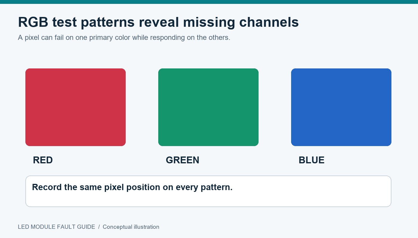
A white field can help reveal a color cast across adjacent cabinets. Use the level approved for the setup and repeat the comparison at the planned brightness. Then view low-gray content from the same position. A wall can look even on white while a cabinet boundary remains visible in shadows. If your project has a numerical uniformity requirement, agree on an instrument, pattern level, measurement points, and viewing geometry. A photograph helps document the location of a mismatch, while exposure and white balance can change how the mismatch looks.
3. Compare the Built-In Pattern With the Player Output
Start with geometry. For a native-resolution LED wall test pattern, build the file using the exact active pixel dimensions of the assembled wall. Check that the playback software and processor preserve one source pixel per wall pixel for that test. A laptop set to a different output size or a processor that resizes the input can soften a one-pixel grid before the cabinets receive it. Check the active input format on the processor as well as the file properties.
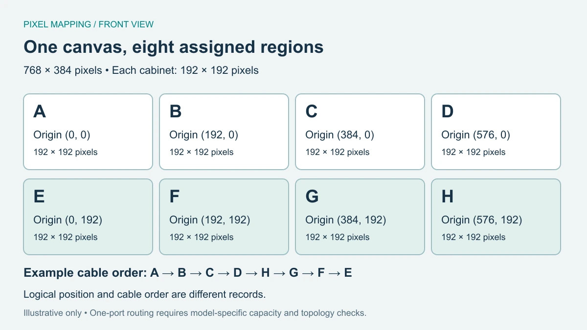
If a numbered grid puts a cabinet label in the wrong place, compare the visible label with the front-view cabinet drawing and check how the receiving card is assigned. Record coordinates from the audience side so a technician looking at the back of the wall can translate them correctly. If a line breaks at a seam while the cabinet labels and coordinates agree, ask the supplier to inspect the physical joint and module seating alongside the display settings.
When the built-in LED wall test pattern looks correct and the external copy shows the problem, start by checking the external route and the settings it adds. For example, a missing border may come from a crop or fit setting in the player or processor. If both patterns show the same stationary mark and both reach the same cabinet through a shared path, investigate the shared path first. This narrows the investigation. A shared symptom can still have several causes, as the module fault guide shows for lines and color shifts.
For a remote demo, ask the operator to show the input status screen before playing each LED wall test pattern. Keep the camera position and exposure steady for the comparison. Capture one whole-wall view and one closer view of the affected position. For an on-site check, use the intended audience distance and replay representative slides or video at the end. Save the test asset and configuration names so the supplier can reproduce a result on the same hardware. For a factory visit, EagerLED'S quality-control checklist covers the production records to review alongside the demonstration.
4. Check Shadow Detail at Working Brightness
Use a stepped grayscale pattern alongside a smooth ramp when dark detail matters. The steps give observers fixed patches to refer to in their notes. The ramp shows where a transition breaks into bands or picks up a tint. Load both through the proposed player with the room lighting set for normal operation. Run them again using a representative dark scene from the client’s content. Hold the same display preset for all three observations.
A scene with both bright highlights and dark textures helps reveal whether shadow detail remains legible in ordinary content. Use a scene like this alongside the ramp, then judge the actual wall with known test levels.
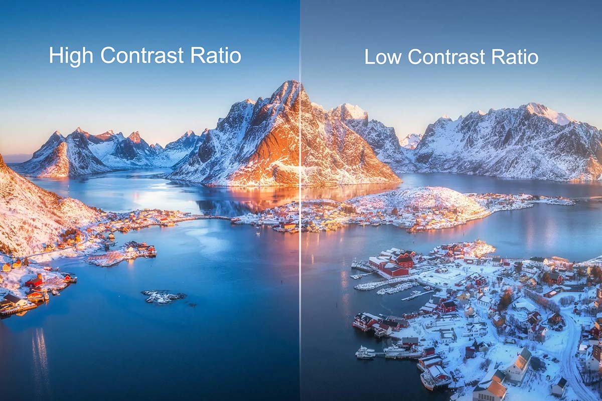
If the darkest patches merge across the entire wall, check the player’s output range and the processor’s input interpretation before adjusting the display. A full-range signal interpreted as limited range can clip dark values. Confirm how the two devices handle the actual signal format, because labels and automatic detection vary. If the discontinuity stays in one physical area while the same patches remain distinct elsewhere, record its cabinet coordinates. Ask the supplier to check the approved calibration profile and compare adjacent cabinets at that same output level.
For example, a conference room may use one preset during presentations and a dimmer one during video playback. A supplier can demonstrate the same ramp under both approved presets and record which patches remain distinct at the front seating position. Note the input format, preset name, and viewing position with each result. Those records give the installer a repeatable LED wall test pattern check during handover.
FAQ
Can I use a screenshot from a website as a test file?
A screenshot can illustrate a test concept. For a pixel-level check, create or export the pattern at the wall’s exact active resolution. Browser zoom, compressed images, and playback scaling can all blur the edges you are trying to inspect.
Does a clean static pattern prove the wall will look clean on camera?
Camera acceptance needs a separate check with the intended camera, lens, distance, and exposure settings. Record moving footage and the display settings in use. A still pattern viewed in the room provides no observation of what the camera records during a moving shot.
Can I compare two display samples using different brightness presets?
For a fair comparison, ask the supplier to set a comparable measured light output where practical and record the target and measurement method. Identical percentage settings can produce different light levels on different models. Keep room lighting and viewing position consistent as well.
Which settings should stay fixed when a supplier retests a fault?
Keep the test asset version, input path, wall preset, and observation position fixed. Record the single change made for the retest, such as a corrected cabinet assignment or a replacement module. This helps you tell whether that change explains the result.
What to Send Before a Display Demo
Send your target dimensions, proposed cabinet grid if available, nearest viewing distance, a sample content file, and a description of the room lighting. If you have a visible fault to reproduce, include the input used and the cabinet position. Ask for an LED wall test pattern suited to that symptom and a second pass through your intended playback path. Share your demo requirements with EagerLED so the proposed display, controller, and source can be discussed together.
 Rimorchio con schermo LED: cosa controllare prima di acquistarne o costruirne uno